
Musical drum practice pads

a technology of drums and pads, applied in the field of musical instruments, can solve the problems of a large amount of time and effort, and the sound generated by the device remains relatively loud, and achieves a large amount of bounce or rebound. , to achieve the effect of convenient use and inexpensive manufacturing

Inactive Publication Date: 2005-12-29
REMO INC
View PDF15 Cites 6 Cited by
  • Summary
  • Abstract
  • Description
  • Claims
  • Application Information

AI Technical Summary

Benefits of technology

"The present invention provides an improved practice pad device that can simulate the playing surface response characteristics of conventional percussion instruments such as snare drums, tom-toms, bass drums, cymbals and the like. The device includes one or more metal base members with percussion pad members attached to them using magnetic coupling. The percussion pad members have response characteristics that match those of the percussion instruments they are meant to imitate. The device is portable, includes individual percussion members with varying thickness, diameter, weight, and playing surfaces that can be used with wire drum brushes. The device is easy to use and inexpensive to manufacture."

Problems solved by technology

Still, the sound generated by this device remains relatively loud.
This is an extremely difficult and burdensome task, in terms of time and effort, to achieve.
Though generally quiet, this pad produces a great deal of bounce or rebound, providing limited usefulness.
Also, the pad is not easily removed and replaced with a substitute to produce a different sound and / or “feel”.
Yet, these pads also have limited usefulness.
Other types of electronic pads, which employ an electronic trigger or pick-up device, are complex and expensive to produce.

Method used


Image

  • Musical drum practice pads
  • Musical drum practice pads
  • Musical drum practice pads

Examples


Embodiment Construction

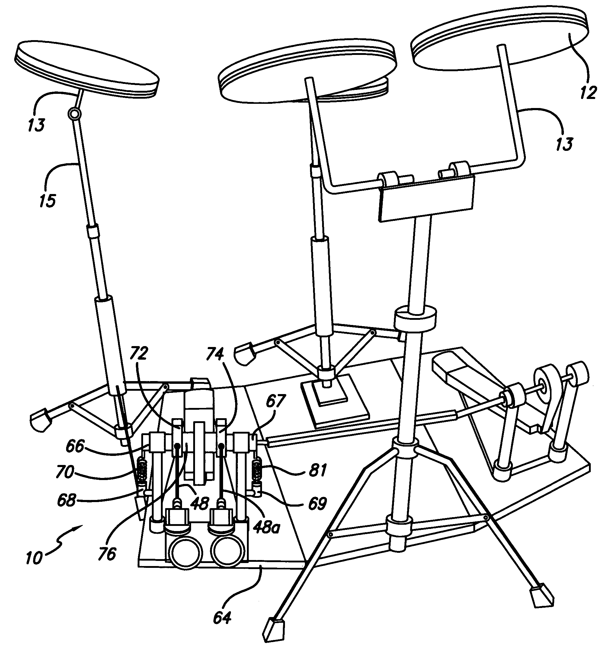
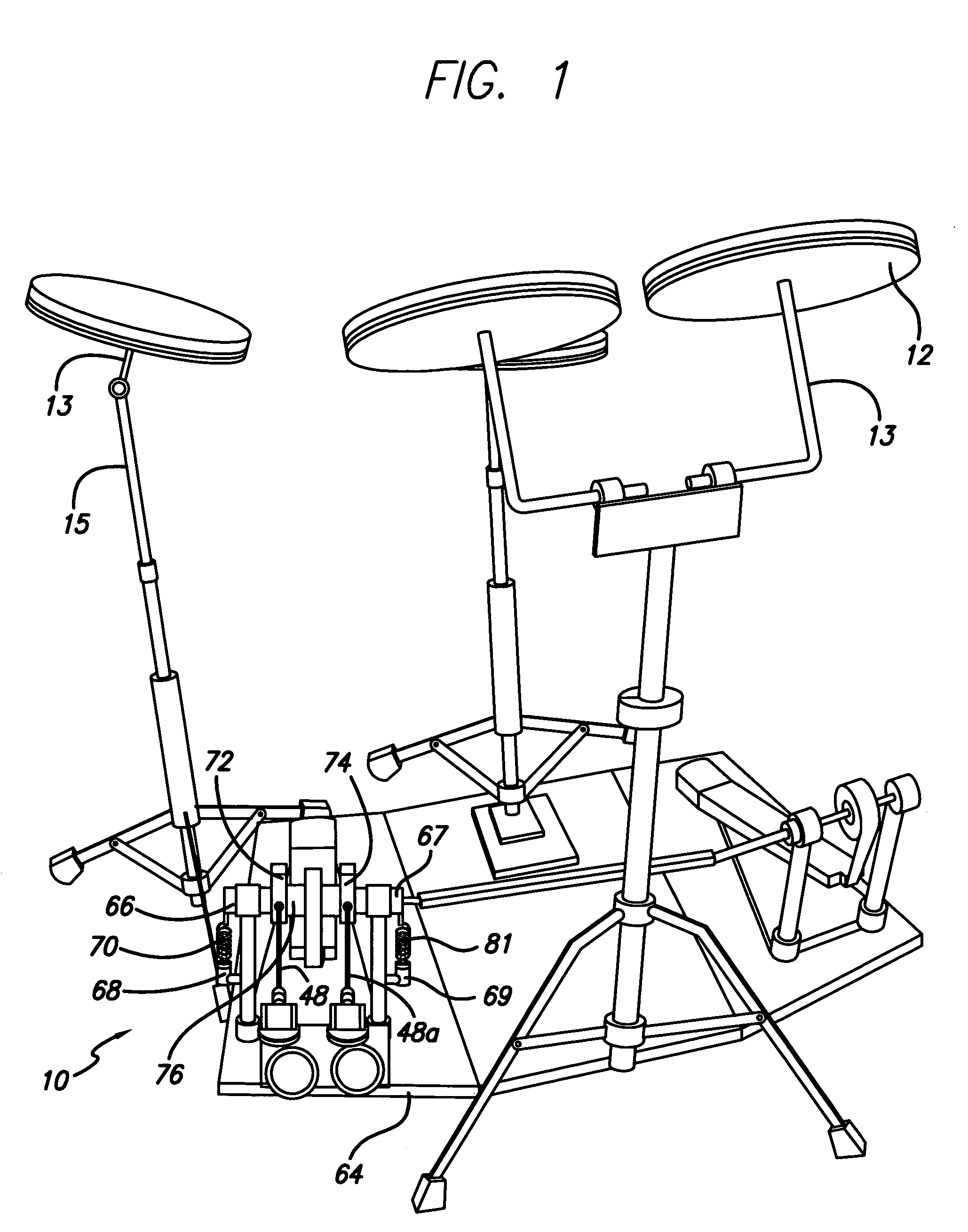
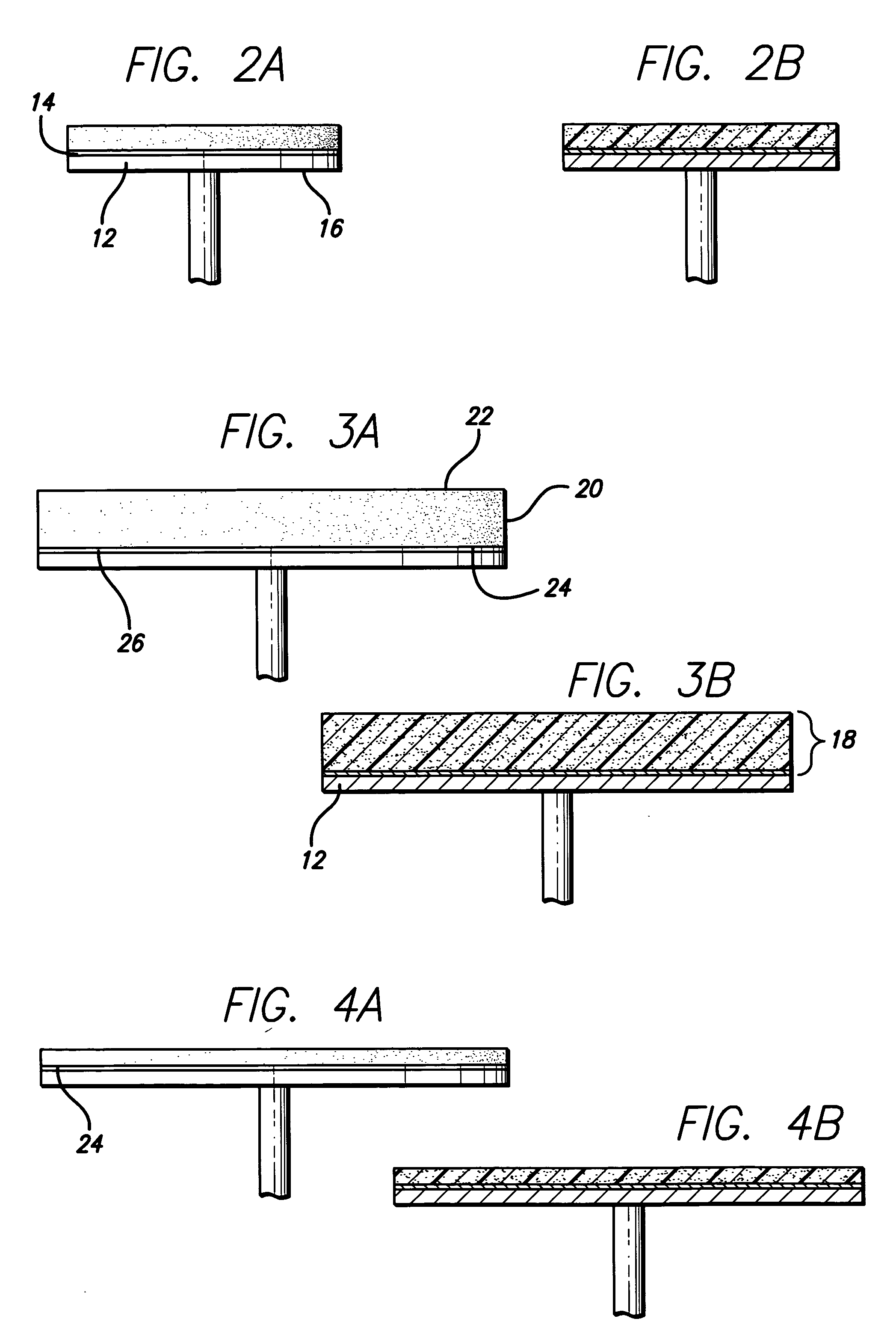
[0034] Referring more particularly to the drawings, FIG. 1 is a perspective view of the preferred embodiment of the present invention depicting a musical drum practice pad apparatus 10 for use in simulating the playing surface response characteristics of conventional percussion instruments, including, without limitation, snare drums, tom-toms, bass drums, cymbals and the like (not shown). Apparatus 10 includes one or more metal base members 12 having a top surface 14 and a bottom surface 16 and one or more percussion pad members 18 individually comprised of a percussion member 20 having an upper surface 22 and bottom surface 24. Also provided is a magnetized pad 26 affixed to the bottom surface 24 of each percussion member 20 for magnetic coupling with top surface 14 of a metal base member 12. Each percussion member 20, including specifically upper playing surface 22, possesses individual response characteristics corresponding to the playing surface response characteristics of one o...


PUM


Abstract

An apparatus for simulating the playing surface response characteristics of conventional percussion instruments, such as a snare drum, tom-tom, bass drum, cymbals and the like, comprising one or more metal base members with each base member having a top surface and a bottom surface, one or more corresponding percussion pad members with each percussion pad member comprised of a percussion member with an upper playing surface and a bottom surface and a magnetized pad affixed to the bottom surface of each of the percussion members for magnetic coupling with a metal base member. Each of the playing surfaces of a percussion member has response characteristics corresponding to the playing surface characteristic of a particular conventional percussion instrument and each percussion pad is removably positioned relative to each of the metal base members. Also provided is a device for simulating the playing surface response characteristics of a bass drum including a foot pedal, a pedal attachment position forward of the foot pedal, a pad housing, a bass pad removably insertable within the pad housing, a beater assembly with a beater head for striking the bass head, and a beater pad mounted on the beater head.

Description

FIELD OF THE INVENTION [0001] The present invention relates generally to the field of musical instruments and, more particularly, to an improved drum practice pad apparatus that simulates the playing surface response characteristics of conventional percussion instruments. DESCRIPTION OF THE PRIOR ART [0002] Devices for practicing drumming technique and building strength and resiliency in the fingers, hands and wrists to improve both technique and stamina are well known in the prior art. These devices are commonly referred to as drum practice pads. Some are comprised of a sheet rubber material adhered to a wood base. Others consists of a conventional drumhead tensioned over a drumshell with a round shaped shallow body filled with foam. This device, which includes a tunable head, acts to deaden the sound and vibration produced when the drumhead is struck. Still, the sound generated by this device remains relatively loud. The “feel” of the pad can be adjusted to a limited extent by sim...

Claims


Application Information

Patent Timeline
Patent Type & Authority Applications(United States)
IPC IPC(8): G10D13/02
CPCG10D13/029G10D13/03
Inventor MAY, JAMES H. JR.
Owner REMO INC
Learn More