Drum stand basket with spring adjustment and other features

a drum and basket technology, applied in the field of drum baskets, can solve the problems of heavy weight, difficult storage, and inability of snare drum baskets to collapse, and achieve the effect of compact storage and transportation of drum baskets, less distortion or undistorted sound

a drum and basket technology, applied in the field of drum baskets, can solve the problems of heavy weight, difficult storage, and inability of snare drum baskets to collapse, and achieve the effect of compact storage and transportation of drum baskets, less distortion or undistorted sound

US9721549B2Active Publication Date: 2017-08-01DRUM WORKSHOP

Image

  • Drum stand basket with spring adjustment and other features
  • Drum stand basket with spring adjustment and other features
  • Drum stand basket with spring adjustment and other features

Examples


Embodiment Construction

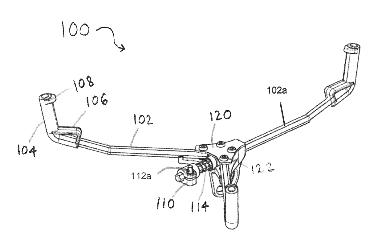
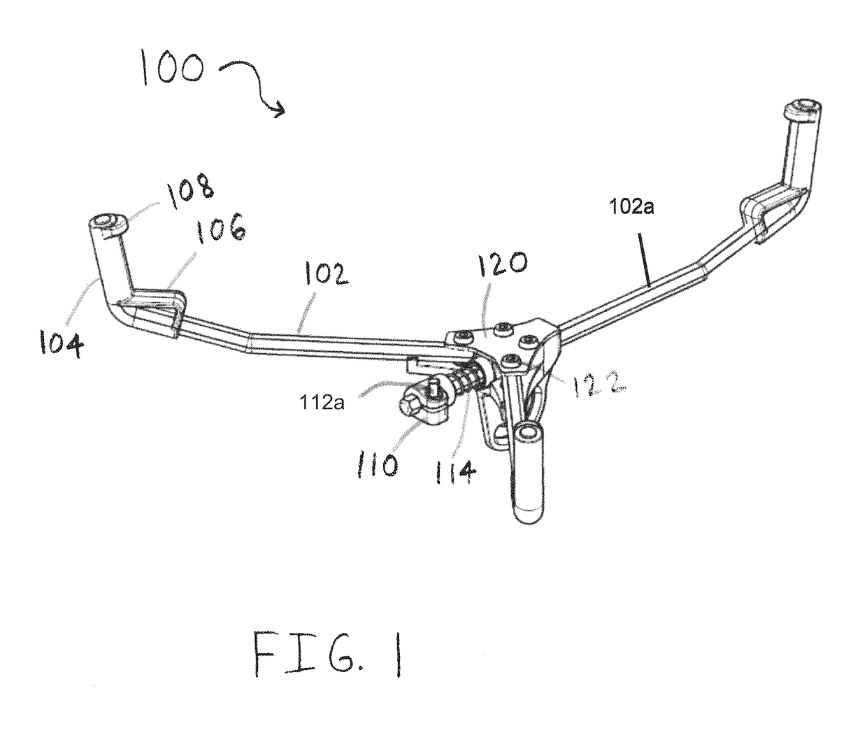
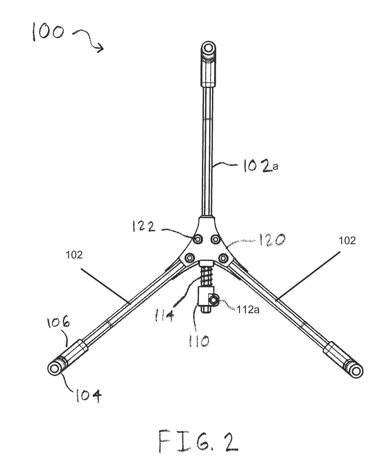
[0025]The present disclosure relates to drum and / or cymbal stands and assemblies, such as snare drum stands, and the snare drum stand baskets. Embodiments of the present disclosure can include features for enabling use with differently sized drums, allowing better sound quality due to a novel drum holding concept, and / or enabling easy compacting and / or storage.

[0026]Throughout this disclosure, the preferred embodiment and examples illustrated should be considered as exemplars, rather than as limitations on the present disclosure. As used herein, the term “invention,”“device,”“apparatus,”“method,”“present invention,”“present device,”“present apparatus” or “present method” refers to any one of the embodiments of the disclosure described herein, and any equivalents. Furthermore, reference to various feature(s) of the “invention,”“device,”“apparatus,”“method,”“present invention,”“present device,”“present apparatus” or “present method” throughout this document does not mean that all clai...


PUM


Abstract

Drum stands and drum stand baskets, including those for use with a snare drum, are described. Drum stands and drum stand baskets according to the present disclosure can include an adjustment feature which enables the basket to fit differently sized drums. Additionally, drum stands and drum stand baskets according to the present disclosure can include elements which result in less interference with the sound of a snare drum compared to a snare drum in a prior art drum stand. Finally, embodiments of the present disclosure can be compacted for easy storage or transport.

Description

[0001]This application claims the benefit of U.S. Provisional Patent Application 62 / 106,166 to Sikra et al., filed on Jan. 21, 2015, which is fully incorporated by reference herein in its entirety.BACKGROUND OF THE INVENTION[0002]Field of the Invention[0003]This invention relates generally to drum stands, and in particular to snare drum stands, and more particularly to snare drum stands and baskets of snare drum stands.[0004]Description of the Related Art[0005]Snare drums are common and widely used percussion instruments. The snare drum can sometimes be the center component and most prominent piece in a drum set. Snare drums are frequently used in orchestras, marching bands, concert bands, parades, drum corps, and many other applications. Because the snare drum is relatively easy to strike, it is highly accessible and often used in teaching.[0006]Snare drums are usually double-sided drums, such that either head of the drum can be struck. Snare drums often come equipped with rattles,...

Claims


Application Information

Patent Timeline
01 Aug 2017
Publication
US9721549B2
IPC
G10D13/02
CPC
G10D13/026; G10D13/02; G10D13/28
Inventors
SIKRA, RICHARD A; STEINHAUSER, RUBEN