Electric sander and motor control therefor

a technology of electric sanders and motors, which is applied in the field of random orbital sanders and orbital sanders, can solve the problems of sanders b>10/b> to jump, undesirable gouges or scratches on the work surface, and and achieve the effect of reducing the height of the sander

Active Publication Date: 2005-11-03
BLACK & DECKER INC
View PDF52 Cites 61 Cited by
  • Summary
  • Abstract
  • Description
  • Claims
  • Application Information

AI Technical Summary

Benefits of technology

[0015] A hand held orbital sander in accordance with an aspect of the invention has a housing having an electronically commutated motor disposed therein and an orbit mechanism disposed beneath the housing. A motor controller is coupled to the motor. The motor controller changes the speed at which it

Problems solved by technology

It has further been determined that if the platen is permitted when unloaded to attain rotational speeds substantially above normal operating speeds—e.g., above approximately 1200 rpm—the rapid deceleration that results when the platen is reapplied to the workpiece causes the sander 10 to jump which can produce undesirable gouges or scratches in a work surface.
One disadvantage the electrically powered random orbital sanders have compared to pneumatic sanders is due to the height of the sander.
In electrically powered random orbital sanders, if the user grasps the sander by placing the palm of the user's hand over the top of the sander, the user's hand is sufficiently far from the work that the user is sanding to cause more fatigue than is the case with p

Method used


Image

  • Electric sander and motor control therefor
  • Electric sander and motor control therefor
  • Electric sander and motor control therefor

Examples


Embodiment Construction

[0036] The following description of the preferred embodiment(s) is merely exemplary in nature and is in no way intended to limit the invention, its application, or uses.

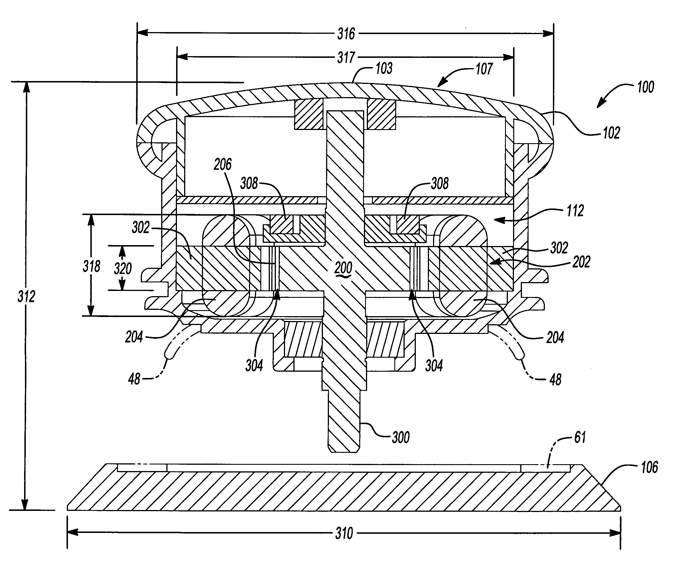
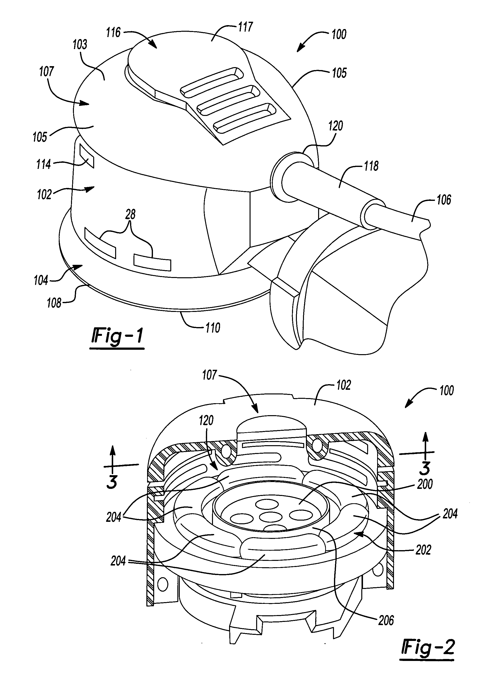
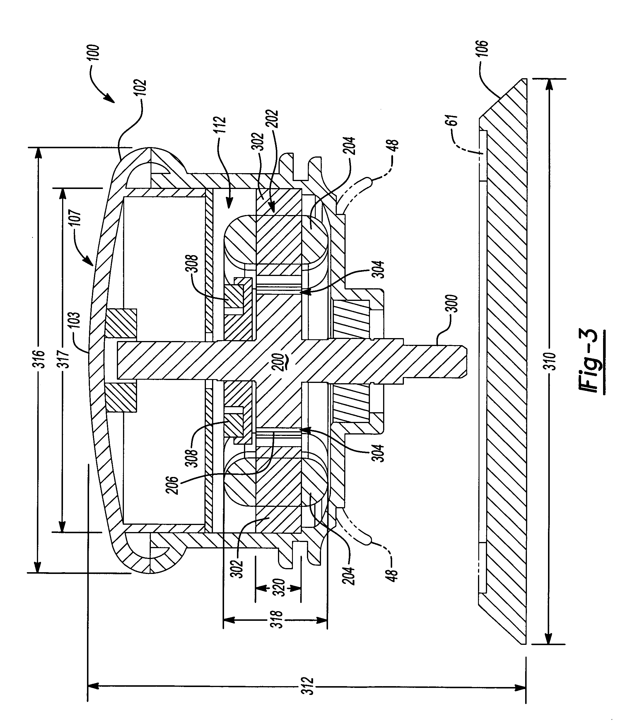
[0037] Referring to FIGS. 1-3, a low profile power tool 100 is shown. Low profile power tool 100 will be described in the context of a random orbital sander and will be referred to as sander 100, but it should be understood that it can be other types of power tools where holding the power tool near where it contacts the work piece would be advantageous, such as orbital sanders (which are sometimes known as “quarter sheet” sanders”).

[0038] Sander 100 includes a housing 102 and an orbit mechanism 104 disposed beneath housing 102. A dust canister 106 may illustratively be removably secured to housing 102. Orbit mechanism 104 and dust canister 106 may illustratively be conventional orbit mechanisms and dust canisters that have been used on prior art orbital sanders, such as disclosed in the above referenced U.S. Pat. N...


PUM


Abstract

A hand held orbital sander has a housing having an electronically commutated motor disposed therein and an orbit mechanism disposed beneath the housing. A motor controller is coupled to the motor. The motor controller changes the speed of at which it runs the motor from an idle speed to a sanding speed upon the motor speed dropping from idle speed to an idle speed threshold value and changes the speed at which it runs the motor from sanding speed to idle speed upon the motor speed increasing from sanding speed to a sanding speed threshold value. The sander may have a mechanical brake that brakes the orbit mechanism and the motor controller also dynamically brakes the motor.

Description

CROSS-REFERENCE TO RELATED APPLICATIONS [0001] This application claims the benefit of U.S. Provisional Application No. 60 / 561,808, filed on Apr. 13, 2004. The disclosure of the above application is incorporated herein by reference.FIELD OF THE INVENTION [0002] The present invention relates to power tools, and more particularly to random orbital sanders and orbital sanders. BACKGROUND OF THE INVENTION [0003] Orbital sanders, such as random orbital sanders, are used in a variety of applications where it is desirable to obtain an extremely smooth surface free of scratches and swirl marks. Such applications typically involve wood working applications such as furniture construction or vehicle body repair applications, just to name a few. [0004] Random orbital sanders typically include a platen that is driven rotationally by a motor-driven spindle. The platen is driven via a freely rotatable bearing that is eccentrically mounted on the end of the drive spindle. Rotation of the drive spind...

Claims


Application Information

Patent Timeline
IPC IPC(8): B24B23/00B24B23/03
CPCB24B23/03
Inventor DESHPANDE, UDAY S.GORTI., BHANUPRASAD V.WAIKAR, SHAILESH P.HILSHER, WILLIAM F.
Owner BLACK & DECKER INC
Why Eureka
Try Eureka