Split ball valve

a ball valve and valve body technology, applied in the direction of fluid removal, sealing/packing, borehole/well accessories, etc., can solve the problems of limiting the control of the drilling or production fluid operations to the whole well bore, the casing or the tubing string is subject to high levels of compressive and tensile stress, and the drilling engineer cannot independently control the drilling or production fluid at different depths within the well bor

Inactive Publication Date: 2005-11-17
SUNSTONE
View PDF17 Cites 31 Cited by
  • Summary
  • Abstract
  • Description
  • Claims
  • Application Information

AI Technical Summary

Benefits of technology

[0008] The present invention, which meets the needs identified above, is a split ball valve positioned down hole (i.e. in a production string in a well bore). The split ball valve comprises an upper valve assembly and a lower valve assembly. The upper valve assembly comprises an upper housing, an upper collar, a plurality of longitudinal supports, and a lower collar. The lower valve assembly comprises a lower housing, a valve body comprising a valve lower body and a valve upper body, two pinion gears, and two valve doors. The two valve doors are located within the valve body. Each of the valve doors are connected to a pinion gear that extends out of the valve body. The pinion gears intermesh with racks on the plurality of longitudinal supports. The longitudinal supports are affixed to a lower collar, an upper collar, and an upper housing. The upper valve assembly can be vertically displaced relative to the lower valve assembly. A spring is positioned between the lower collar and a lower housing collar. The spring keeps the upper valve assembly extended away from the lower valve assembly and thus keeps the valve doors closed.

Problems solved by technology

However, placing the valve at the surface limits the control of the drilling or production fluid operations to the well bore as a whole.
In other words, when the valve is located at the surface, the drilling engineer cannot independently control the drilling or production fluid at different depths within the well bore.
For example, when drilling or producing a well, the casing or tubing string is subjected to high levels of compressive and tensile stress.
If the drilling or production fluid pressure drops below the reservoir pressure, then the formation can blowout into the well bore and create a hazardous condition.
Several types of valves, such as globe valves (See FIG. 1A), angle valves (See FIG. 1B), diaphragm valves (See FIG. 1C), and butterfly valves (See FIG. 1D), create an unacceptable pressure drop across the valve because the valve redirects the fluid around structures within the valve.
While the '667 patent and the '807 patent disclose a ball valve that can be installed in the circulation path of the drilling or production fluid, the '667 patent and the '807 patent do not disclose a ball valve that can be placed down hole.

Method used


Image

  • Split ball valve
  • Split ball valve
  • Split ball valve

Examples


Embodiment Construction

[0023] As used herein, the term “casing” shall mean a plurality of connected cylindrical members that are permanently affixed in the well bore and are used in drilling and production operations.

[0024] As used herein, the term “drill pipe” shall mean a plurality of connected cylindrical members that are connected to a drill bit and are rotated to drill the well bore.

[0025] As used herein, the term “line pipe” shall mean a plurality of connected cylindrical members that are positioned on the surface and are used to transport drilling and production fluid to / from the well bore.

[0026] As used herein, the term “tubing” shall mean a plurality of connected cylindrical members that are removably positioned within the well bore and are used in production operations.

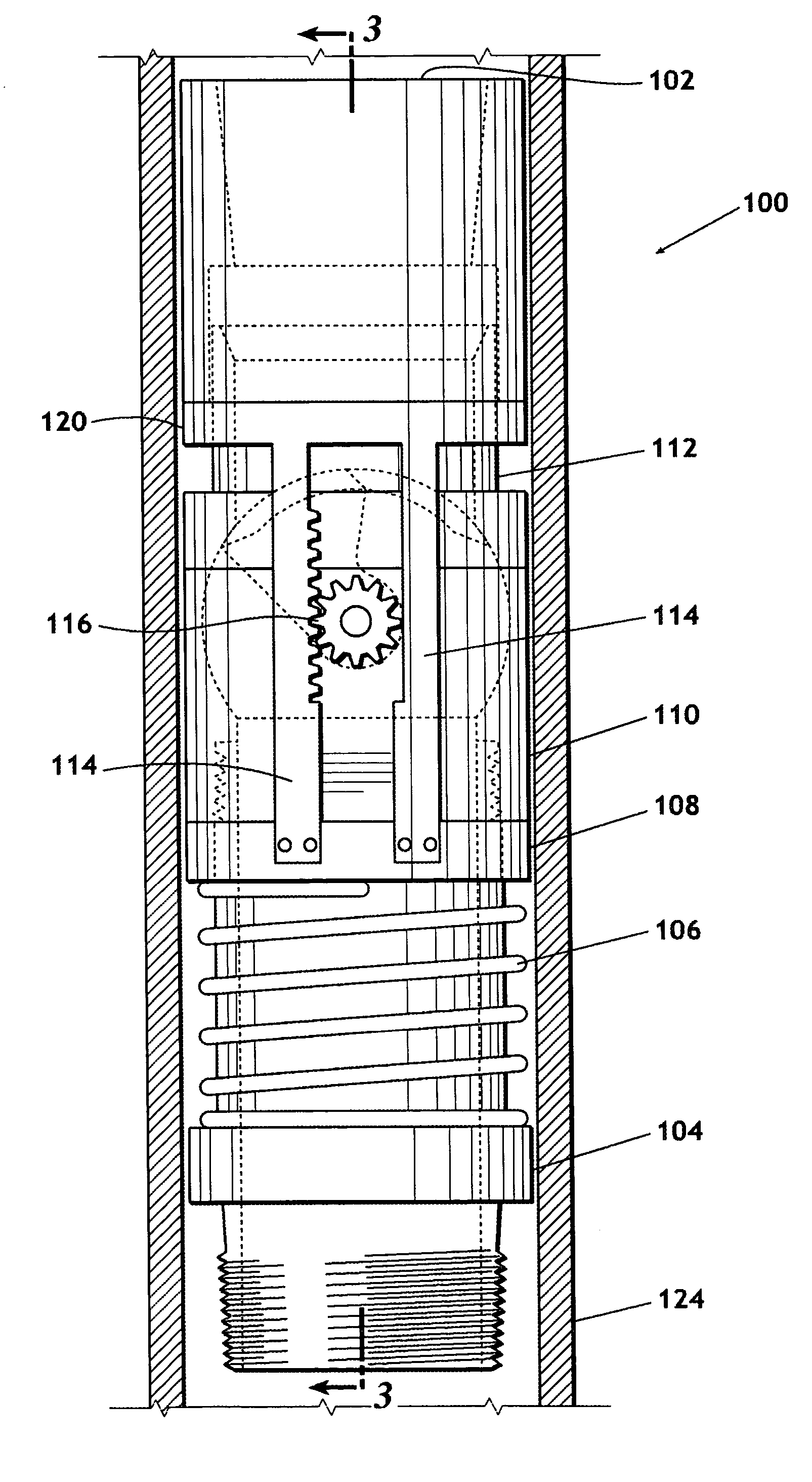
[0027]FIG. 2 is an illustration of an elevation view of split ball valve 100. Split ball valve 100 is shown inside a concentric string of casing 124, which is cutaway in FIG. 2 to show the exterior of split ball valve 100. For...


PUM


Abstract

A split ball valve that may be positioned in a production string of line pipe, casing, or tubing. The split ball valve comprises a lower valve assembly and an upper valve assembly. Each of two valve doors in the lower valve assembly is connected to a pinion gear that intermeshes with racks on the upper valve assembly. The upper valve assembly can be vertically displaced relative to the lower valve assembly. A spring keeps the upper valve assembly extended away from the lower valve assembly and thus keeps the valve doors closed. When a downward force is applied to the upper valve assembly, the upper valve assembly is downwardly displaced causing the pinion gears to rotate, which opens the valve doors. The valve doors recede into cavities in the valve body. When open, the split ball valve is fully ported.

Description

FIELD OF THE INVENTION [0001] The present invention relates generally to piping valves and specifically to a down hole ball valve operated by vertical displacement of an independent string of casing or tubing. BACKGROUND OF THE INVENTION [0002] When drilling or producing a subterranean well, it is often desirable to stop the flow of drilling or production fluid within the production line pipe, casing, or tubing. For example, a drilling engineer may want to stop the flow of drilling or production fluid within the line pipe, casing, or tubing in order to stop the flow of drilling or production fluid into a concentric string of casing or tubing. A drilling engineer may also want to stop the flow of drilling or production fluid within the line pipe, casing, or tubing in order to stop the circulation of drilling or production fluid within a section of the well bore. The most efficient method for stopping the flow of drilling or production fluid within the line pipe, casing, or tubing is ...

Claims


Application Information

Patent Timeline
Patent Type & Authority Applications(United States)
IPC IPC(8): E21B34/12E21B34/14
CPCE21B34/12
Inventor HUGHES, WILLIAM JAMESEILERTSEN, BJORN ARVID
Owner SUNSTONE
Why Eureka
Try Eureka