
Fiber-optic based automatic fire-suppression controller

Inactive Publication Date: 2005-11-17
OLSON MARK PETRUS +1
View PDF4 Cites 9 Cited by
  • Summary
  • Abstract
  • Description
  • Claims
  • Application Information

AI Technical Summary

Benefits of technology

[0014] The presented invention eliminates or lessens the impact of the aforementioned negatives through simplicity of design and use. The pr

Problems solved by technology

These systems are fairly complex and have yet to become available to the general public.
The light transmission property changes drastically as the cable is heated and then ultimately damaged.
This design is also complex and does not lend itself to use by the general public.
In each of the aforementioned designs, there is a singular, glaring drawback.
The majority of annual loss to fire, be it to life or property, occurs in home and business.
The numerous disadvantages of these designs may well explain this:
(1) The aforementioned designs are, as a whole, fairly complex.
This tends to make any one of them difficult and therefore expensive to manufacture.
This in turn makes the finished product somewhat cost prohibitive to the general public.
Furthermore, the more complex the system, the greater the odds of premature failure.
Contaminants will impair the sensor or cause false alarms without regular and dedicated maintenance.
Therefore, a single light sensor is severely limited and ineffective.
In order to incorporate this maxim with the tracking design, an elaborate and expensive computer system would need to be linked.

Method used


Image

  • Fiber-optic based automatic fire-suppression controller
  • Fiber-optic based automatic fire-suppression controller
  • Fiber-optic based automatic fire-suppression controller

Examples


Embodiment Construction

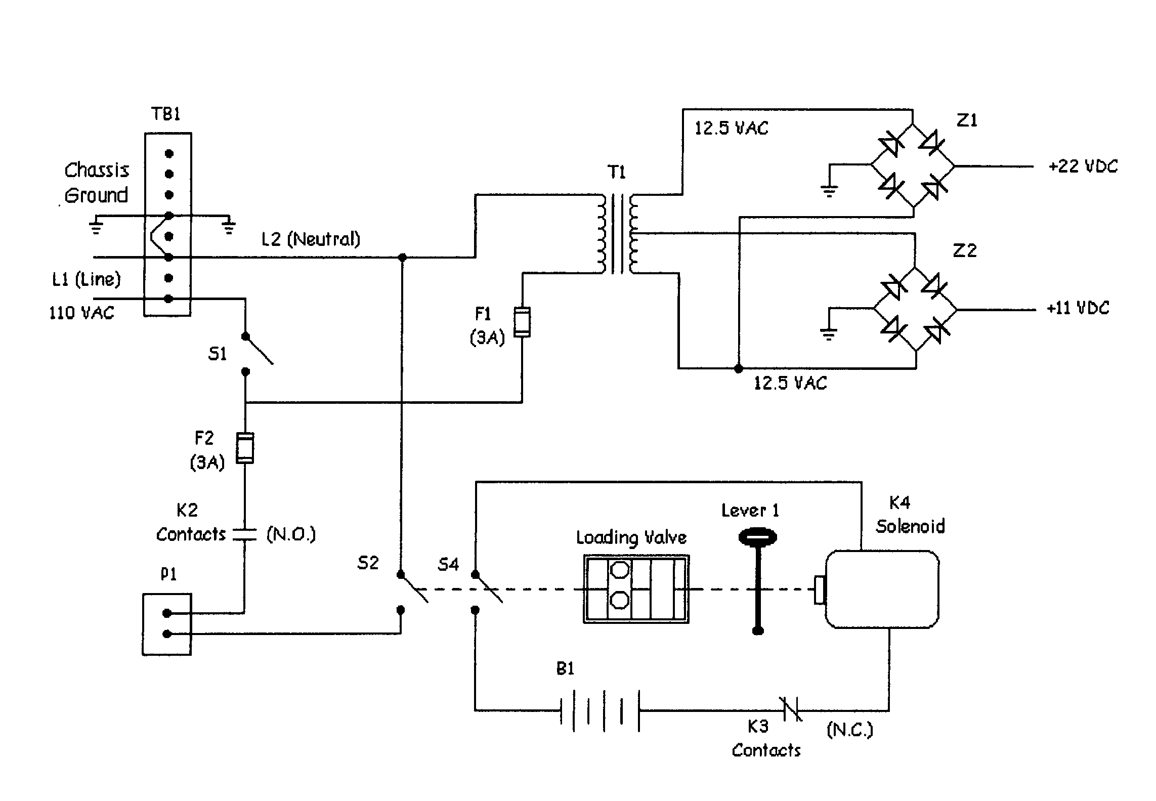
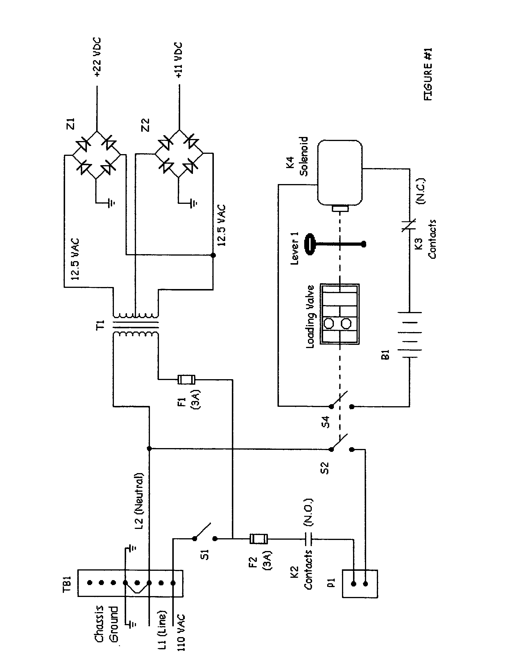
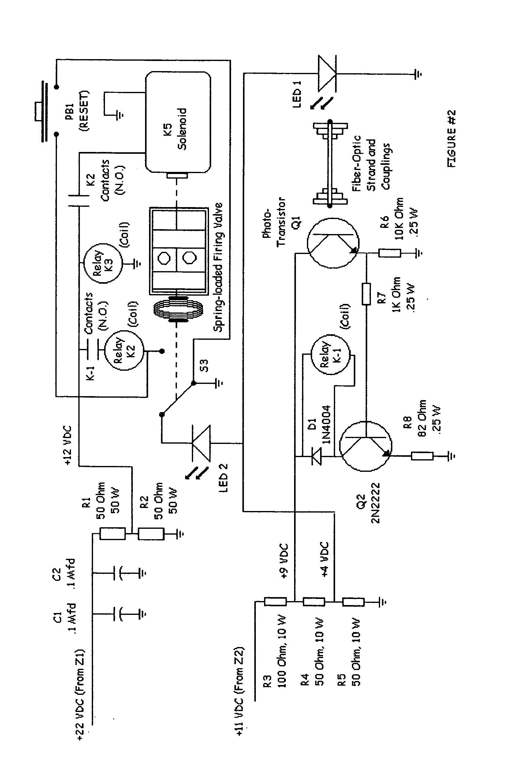
[0066] As the present invention is an Electro-mechanical system, a preferred embodiment is shown in FIGS. 1 and 2, that being a complete electrical schematic.

[0067] Commercially available 110 Volt A / C power is supplied to the system at TB1. 14 gauge, 2-conductor electrical cable with ground is required for a permanent installation of the present invention. The system power can then be manually controlled by externally mounted toggle switch, S1. Internal circuitry provides the necessary power needed to operate externally mounted Photo-transmitter LED 1 and externally mounted Phototransistor Q1. One end of a length of external unshielded Fiber Optic strand is centrally mounted directly in front of LED 1. The opposite end of the external Fiber Optic strand is centrally mounted directly in front of Q1. The sealed construction of these connections is such that contamination of the Fiber Optic strand is prevented. The Fiber Optic strand is then routed so as to be in close proximity of al...


PUM


Abstract

An Electro-mechanical device utilizing a fiber optic based sensor (Fiber Optic strand) for the purpose of detecting and extinguishing a fire momentarily after ignition. A light signal transmitted through the sensor (Fiber Optic strand) is used as a means to urge a spring loaded valve (Firing Valve) against its established position, thus blocking the dispersal of fire suppressing agents. This condition will persist until the sensor (Fiber Optic strand) is damaged by the presence of open flame in close proximity.

Description

CROSS-REFERENCE TO RELATED APPLICATIONS [0001] Not applicable. BACKGROUND [0002] 1. Field of Invention [0003] This invention relates to fire extinguishing systems, specifically those that do not require monitoring or operating personnel. [0004] 2. Description of Prior Art [0005] Fire extinguishers and fire-suppression systems are widely used in both residential and industrial constructions. The effort to halt or minimize the huge annual losses to life and property has been ongoing for decades. Both extinguishers and systems are numerous and varied. They range from simple hand-held units to vast built-in networks. [0006] Modern designs are for the most part both obvious and familiar. One innovation has been the incorporation of Fiber optic cable as a sensor. The light transmission properties of Fiber optic cable make an ideal sensor. There are several prior art references to this, being; U.S. Pat. No. 6,044,913 to Stehling, et al (2000), U.S. Pat. No. 6,164,383 to Thomas (2000), U.S....

Claims


Application Information

Patent Timeline
IPC IPC(8): A24F25/00A61L9/04A62C35/00A62C37/36G01J1/04G08B17/02G08B17/103
CPCA62C37/36G08B17/103G08B17/02
Inventor OLSON, MARK PETRUSHILDERBRANDT, RICHARD LEE
Owner OLSON MARK PETRUS
Learn More