
Vehicle with two parallel wheels

Inactive Publication Date: 2009-08-06
TOYOTA JIDOSHA KK
View PDF5 Cites 10 Cited by
  • Summary
  • Abstract
  • Description
  • Claims
  • Application Information

AI Technical Summary

Benefits of technology

[0004]In accordance with the step clearing wheels having such structure of Patent document 1, it produces an advantageous effect that “it allows a compact design by integrally-mounting the leg member of the invention in the middle portion, and thereby solves the problems; therefore, it can be compatible with conventional casters” (Advantageous effect of the invention in the specification) or similar advantageous effects.
[0005]Furthermore, Patent document 2 describes a second example of a vehicle with two parallel wheels in related art. Patent document 2 describes a wheelchair capable of safely and reliably overriding a step. The wheelchair described in Patent document 2 is characterized by that “in the wheelchair comprising a frame having a seat for a rider and equipped with pairs of front wheels and rear wheels, the wheelchair further comprises a footrest having substantially the same width as the wheelchair, the footrest comprising an upper side where the rider puts its feet and an under side contact surface for contacting the corner of a step, the footrest being located between the front wheels and mounted on the frame through a substantially horizontal pivot, the pivot being perpendicular to the moving direction of the wheel chair, and the footrest being rotatable between the regular position where the contact surface is located in front of the front wheels and retract position where the contact surface intersects with the lower periphery of the front wheel”.
[0006]In accordance with the wheel chair having such structure of Patent document 2, it produces an advantageous effect that “when the rider drives the rear wheels after the wheel chair moves forward until the contact surface contacts the corner of a step with the footrest being in the regular position, the footrest is retract to the retract position against a bias mean so that the front wheels can run on the step, and thereby the rider can further drive the rear wheels to move the entire wheel chair above and past the step” (Paragraph [0021] in the specification) or similar advantageous effects.
[0007]Furthermore, Patent document 3 describes a third example of a vehicle with two parallel wheels of in related art. Patent document 3 describes a free wheel used as a front wheel capable of smoothly clearing a step and lessening the impact caused by the contact with the step. The step clearing wheel described in Patent document 3 is characterized by that “in a free wheel for a self-propelled vehicle or a carriage, a main wheel is arranged eccentrically by an pivot, and support wheels are arranged ahead of the main wheel on the left and right sides; and the step clearing wheel further comprises a cushion device for lessening the impact caused by the contact with the step”.
[0008]In accordance with the step clearing wheel of Patent document 3, it produces an advantageous effect that “when the wheel encounters a step, the support wheels first hit the step, position the main wheel body perpendicularly to the step, and then runs on the step; at this point, the main wheel (2) does not sustain the weight, and the main wheel (2) starts to run on the step from the position where the support wheels (3) is raised from the ground; furthermore, it clears the step using the cushion to lessen the impact occurring from the contact to the step; and therefore, when it is used for a wheelchair, is can clear a step by forward propulsion force alone regardless of the size of a step” (Paragraph [0006] in the specification) or similar advantageous effects.[Patent document 1] Japanese unexamined patent application publication No. 2002-2206[Patent document 2] Japanese unexamined patent application publication No. 2005-296606[Patent document 3] Japanese utility model registration No. 3105824
[0009]However, the step clearing wheel of Patent document 1 is used as a component for transfer equipment. In other word, it is used as a support wheel for clearing a step in a vehicle such as a wheelchair and a baggage transfer vehicle which has 3 or 4 wheels. Furthermore, the wheelchair of Patent document 2 relates to a four-wheel vehicle (wheelchair) which has two front wheels of a smaller diameter and two rear wheels of a larger diameter, and particularly, relates to a wheelchair having a step clearing means capable of sufficiently sustaining the load during the step clearing action. Furthermore, Patent document 3 describes a front free wheel which enables a wheelchair or a handcart to smoothly clear a step and lessens the impact by a cushion.

Problems solved by technology

Therefore, there has been a problem that it requires torque three or four times as large as that needed when driving on a flat place, and thereby requires a driving source capable of producing large driving force.
However, there is a problem that when such kind of step run-on assist mechanisms is used in a two wheeled vehicle, the driving wheel will be raised from the ground and spin freely without pushing the ground during a step run-on process.
However, the gas spring is used just for lessening the impact occurring from the contact and is not used for any other purposes.

Method used


Image

  • Vehicle with two parallel wheels
  • Vehicle with two parallel wheels
  • Vehicle with two parallel wheels

Examples


Embodiment Construction

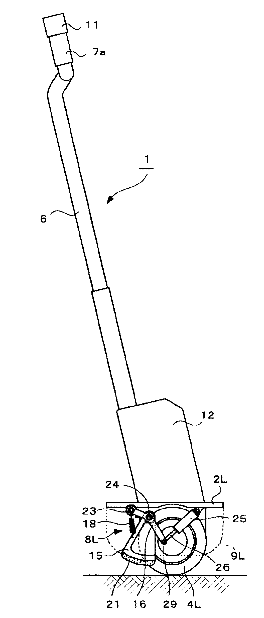
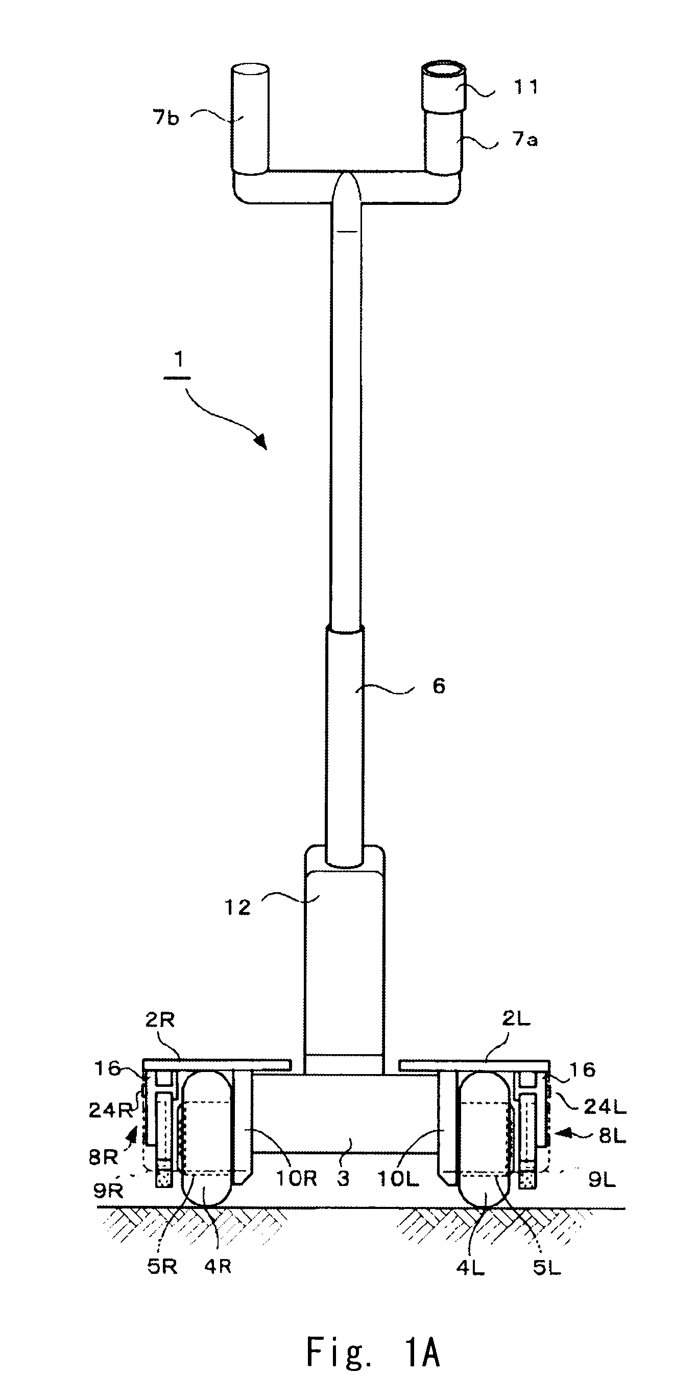
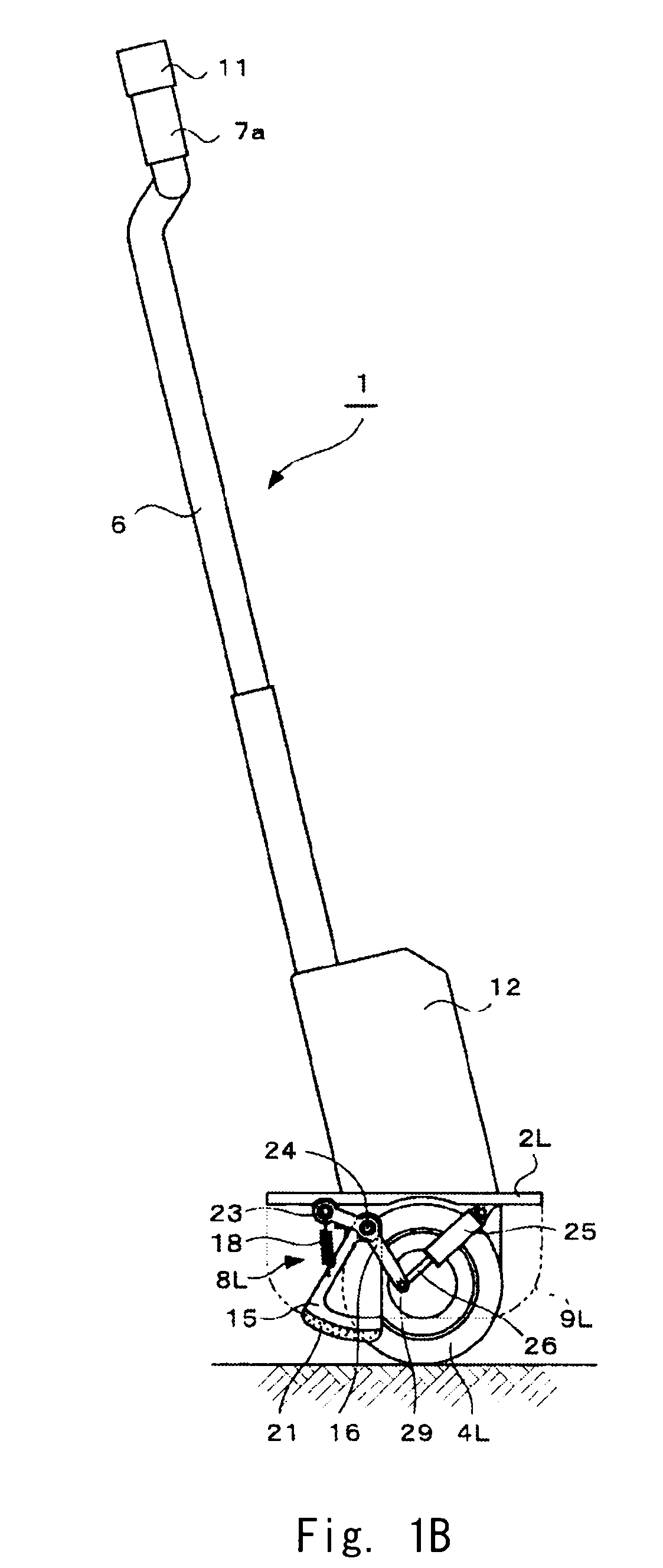
[0031]An assisting turning member having a circular support surface of a curvature radius larger than that of the wheels are arranged such that the turning center of the assisting turning member is ahead of the rotating center of the wheels in the travel direction of the vehicle. The assisting turning member is rotatablly supported by a link member, one end of which is rotatablly supported on a step base or a vehicle body. Furthermore, the other end of the link member is supported on a retaining force changing device capable of changing the retaining force depending on the collision speed of the assisting turning member to a step. With this structure, it can achieve a vehicle with two parallel wheels capable of easily running on a step and easily traveling on a road surface having steps.

[0032]Embodiments of the present invention are explained hereinafter with reference to the drawings. FIGS. 1A-7 show embodiments of the present invention as examples. That is; FIGS. 1A and 1B are a f...


PUM


Abstract

A vehicle with two parallel wheels according to the invention has split steps (2L, 2R), a vehicle body, a pair of wheels (4L, 4R) coaxially parallelly arranged, a pair of wheel drive units for independently driving the wheels (4L, 4R), and a pair of step run-on assisting mechanisms (8L, 8R) arranged corresponding to the wheels (4L, 4R) and changing the degree of dependency of step run-on operation. The step run-on assisting mechanisms (8L, 8R) each have an assisting turning member (15) having a circular arc support surface with a curvature radius greater than the radius of the wheel (4L, 4R) and having its turning center in front, in the travel direction, of the rotation center of the wheel, a link member (16) rotatably supporting the assisting turning member (15), and a damper (25, 26) for changing, according to the speed at which the assisting turning member (15) collides with a step, force retaining one end of the link member (16).

Description

TECHNICAL FIELD[0001]The present invention relates to a vehicle with two parallel wheels which runs with two parallel-arranged wheels.[0002]In particular, the present invention relates to a vehicle with two parallel wheels equipped with a step run-on assist mechanism to facilitate running on a step.BACKGROUND ART[0003]For example, Patent document 1 describes a first example of a vehicle with two parallel wheels of such kind in related art. Patent document 1 also describes a wheel used as a component of transfer equipment. A step clearing mechanism described in Patent document 1 is characterized by that “in the step clearing mechanism wherein a leg member having a disk shape or irregular shape periphery of a diameter greater than that of wheels used in the caster touches a step and rotates before the wheels themselves touch the step so that it causes the wheels to rise from the ground and run on the step, wherein the one leg member is arranged at the middle of the two wheels and inte...

Claims


Application Information

Patent Timeline
IPC IPC(8): B62B5/02
CPCB62K3/007B62B5/02B62K11/007
Inventor KAKINUMA, TAKEKAZUYAMANO, IKUOKAWARASAKI, YOSHIHIRO
Owner TOYOTA JIDOSHA KK
Learn More