In-wheel motor system

Inactive Publication Date: 2009-05-28
BRIDGESTONE CORP
View PDF2 Cites 55 Cited by
  • Summary
  • Abstract
  • Description
  • Claims
  • Application Information

AI Technical Summary

Benefits of technology

[0024]According to the present invention, the motive power of an electric motor is transmitted to a wheel through the medium of a reduction gear mechanism. And also the motor case supporting the stator side of the motor is floating-mounted with respect to the unsprung portion of a vehicle, with the motor case connected to a knuckle coupled to a wheel section or to a motor mounting member provided on a strut suspending a knuckle from a vehicle body by a shock absorbing member or a shock absorbing mechanism equipped with a spring member and a damper. As a result, the ground contact performance of the vehicle and the riding comfort can be both improved markedly. And if a casing of the reduction gear mechanism is integrally structured together with a knuckle coupled to the suspension mechanism of the vehicle, then it will be possible to replace the motor and the reduction gear mechanism separately. This makes it possible to use the same motor for wheels of different tire diameters or change the output torque by changing the reduction gear mechanism only.
[0025]Also, with the structure of the present invention employed, the motor only will be mounted on the unsprung portion of the vehicle, so that the durability of the power transmission mechanism, such as a flexible coupling, that couples the electric motor to the reduction gear mechanism can be improved.
[0026]Moreover, the reduction gear mechanism may be constituted by a first reduction gear mechanism connected directly to the output shaft of the motor and a second reduction gear mechanism connecting the first reduction gear mechanism to the wheel, and the rotation speed of the el

Problems solved by technology

Generally, however, with vehicles having suspension mechanisms such as springs around the wheels, the greater the so-called unsprung mass, which is the mass of unsprung parts such as wheels, knuckles and suspension arms, is, the worse the road holding performance of the vehicle will be due to variation in the road engaging force of the tire when the vehi

Method used


Image

  • In-wheel motor system
  • In-wheel motor system
  • In-wheel motor system

Examples


Example

Embodiment 1

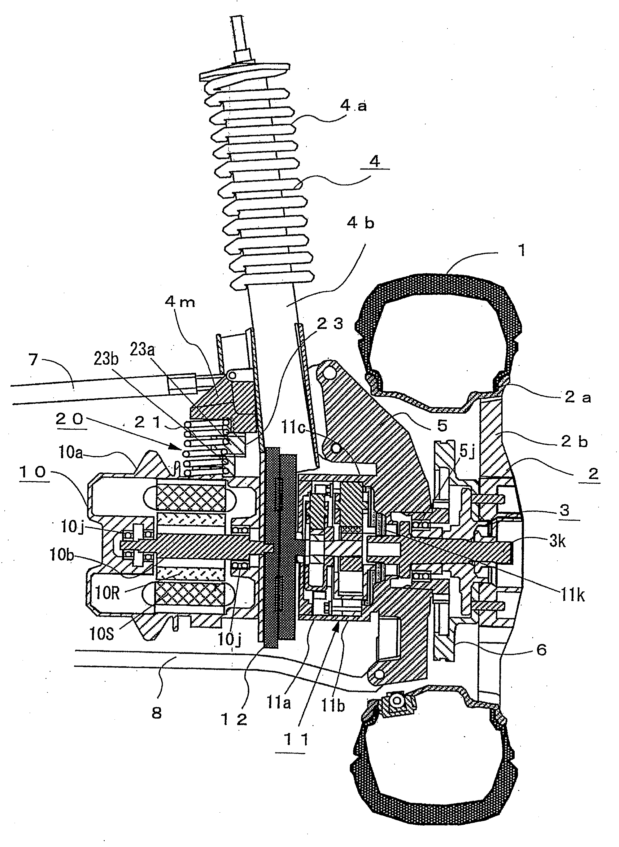
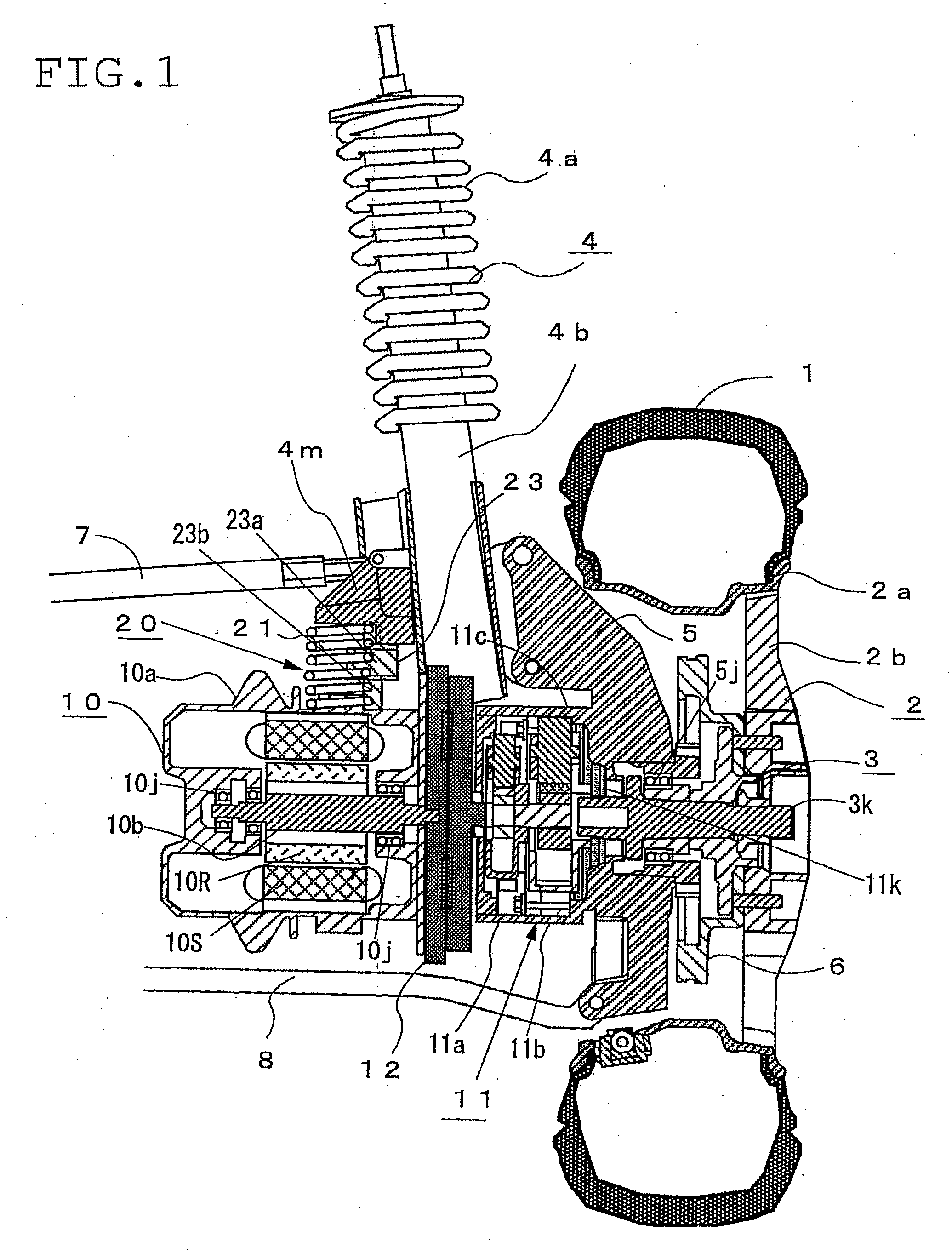
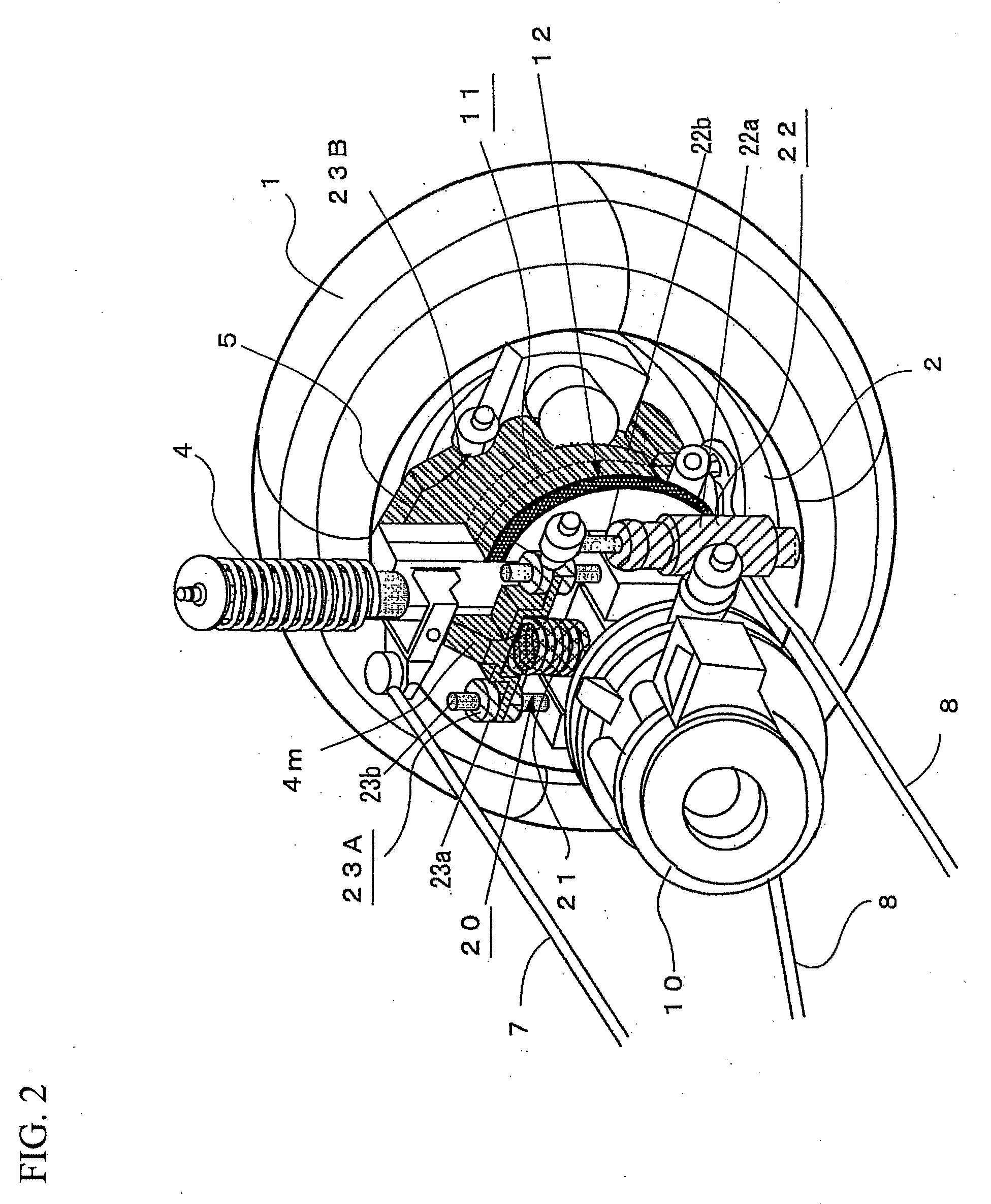
[0078]FIG. 1 is a vertical sectional view showing a structure of an in-wheel motor system according to Embodiment 1, and FIG. 2 is a perspective illustration thereof. In each of the figures, reference numeral 1 denotes a tire, 2 a wheel composed of a rim 2a and a wheel disk 2b, 3 a wheel hub connected to the wheel 2 at the rotary shaft thereof, 4 a strut having a coil spring 4a and a shock absorber 4b and suspending a knuckle 5 connected thereto via the wheel hub 3 and a bearing 5j from a vehicle body, 6 a brake mechanism mounted to the wheel hub 3, 7 an upper arm connected to the strut 4, and 8 a lower arm supporting the knuckle 5 from below.

[0079]Also, reference numeral 10 denotes an electric motor provided with a motor case 10a supporting the stator 10S side thereof, an output shaft 10 rotatably mounted on the motor case 10a by bearings 10j, and a rotor 10R mounted on the output shaft 10b, and 11 denotes a reduction gear mechanism provided with a first planetary gear ...

Example

Embodiment 2

[0093]In Embodiment 1, an electric motor 10 and a reduction gear mechanism 11 are placed in separate casings. And, by providing a motor mounting member 4m on the lower part of a strut 4, a motor case 10a supporting the stator 10S side of the motor 10 is mounted on the motor mounting member 4m through the medium of a shock absorbing mechanism 20. Also, a casing 11c of the reduction gear mechanism 11 is integrally structured together with a knuckle 5. In embodiment 2, however, as shown in FIG. 5 and FIG. 6, an electric motor 10 and a reduction gear mechanism 11 may be coupled with each other by a flexible coupling 12, and a motor case 10a supporting the stator 10S side of the motor 10 may be mounted to the motor mounting member 4m through the medium of a shock absorbing mechanism 20. And also a casing 11c of the reduction gear mechanism 11 may be fixed to a knuckle 5.

[0094]In this embodiment, too, the reduction gear mechanism 11 is separated from the electric motor 10 by t...


PUM


Abstract

An electric motor 10 and a reduction gear mechanism 11 are connected to each other by a flexible coupling 12, such as an Oldham's coupling, which is a power transmission mechanism. Also, a casing 11c of the reduction gear mechanism 11 is integrally structured together with a knuckle 5, which is an unsprung part of a vehicle, or mounted to the knuckle 5. Further, a motor case 10a of the electric motor 10 is mounted to a motor mounting member 4m provided on the lower part of a strut 4 for suspending the knuckle 5 through the medium of a shock absorbing mechanism 20 equipped with a spring member 21, a damper, and two guide members 23 for guiding the operating direction of the spring member 21 and the damper. An in-wheel motor system thus structured allows the mass of the motor 10 to act as the mass of a dynamic damper and thus features not only improved ground contact performance and riding comfort of a vehicle running on a rough road but also superior space efficiency.

Description

TECHNICAL FIELD[0001]The present invention relates to an in-wheel motor system equipped with a wheel driving motor adjoining a wheel and, more particularly, to an in-wheel motor system so structured as to support the motor through the medium of a shock absorbing mechanism or a shock absorbing member with respect to the around-the-wheel parts of a vehicle.BACKGROUND ART[0002]In recent years, in-wheel motor systems are increasingly introduced into motor-driven vehicles such as electric vehicles. Those in-wheel motor systems typically have an electric motor or a geared driving motor or the like, which integrally incorporates an electric motor and a planetary reducer within a motor case, adjoining a wheel.[0003]Generally, however, with vehicles having suspension mechanisms such as springs around the wheels, the greater the so-called unsprung mass, which is the mass of unsprung parts such as wheels, knuckles and suspension arms, is, the worse the road holding performance of the vehicle w...

Claims


Application Information

Patent Timeline
IPC IPC(8): B60K7/00B60K1/00
CPCB60G3/20Y02T10/641B60G13/18B60G15/04B60G2200/144B60G2200/156B60G2200/17B60G2200/42B60G2202/25B60G2202/312B60G2204/129B60G2204/148B60G2204/182B60G2204/30B60G2204/4191B60G2204/4304B60G2206/50B60K7/0007B60K17/02B60K17/046B60K17/30B60K2007/0053B60K2007/0092H02K7/006H02K7/116H02K7/14B60G7/008B60L2220/44B60L2220/46Y02T10/64
Inventor NISHIOKA, SATOSHIIWANO, HARUOTASHIRO, KATSUMI
Owner BRIDGESTONE CORP
Why Eureka
Try Eureka