EGR gas cooling apparatus

Inactive Publication Date: 2005-09-01
USUI KOKUSAI SANGYO KAISHA LTD
View PDF5 Cites 38 Cited by
  • Summary
  • Abstract
  • Description
  • Claims
  • Application Information

AI Technical Summary

Benefits of technology

[0021] The present invention is designed to solve the above-mentioned problems, and it is an object of the present invention to improve the durability of an EGR gas cooling apparatus, specially an EGR valve, by inhibiting the precipitation of the condensate by water vapor, unburned gas, sulfuric acid solution and hydrocarbon contained in the EGR gas or the generation of a moisturized viscous soot having a high bulk density of particles, and to reduce the thermal stress due to the thermal distortion or temperature difference in the EGR gas cooler. Further, it is another object of the present invention to obtain a high quality product having a good durability by keeping the smooth operation property or the air-tightness of the EGR valve by inhibiting the degradation of various parts, by arranging the EGR valve at the location w

Problems solved by technology

From the foregoing reasons, the EGR gas cooler becomes larger and thermal deformation happened, and also there is a possibility the temperature difference between the EGR gas and the refrigerant liquid becomes bigger.
To prevent the metal corrosion due to the condensate, heat conduction pipes, heat conduction plates or materials for brazing is formed with the high anticorrosive material, which causes the increase of cost.
Also, in the heat conduction face, the soot in the EGR gas is deposited simultaneously with the precipitation of the condensate, whereby a moisturized viscous soot layer having a high bulk density of particles is deposited on the heat conduction face, and the soot layer creates a heat insulation effect, which reduces the heat conduction effect of the heat conduction face, so that the efficiency of the heat exchange may be deteriorated.
Due to the high temperature EGR gas, the degradation of the actuator happens, so that the life span of the EGR valve is shortened.
Also, to prevent the leakage of the EGR gas, a high-priced seal member having a high thermal resistance is necessary to e used between the actua

Method used


Image

  • EGR gas cooling apparatus
  • EGR gas cooling apparatus
  • EGR gas cooling apparatus

Examples


Example

[Embodiment 1]

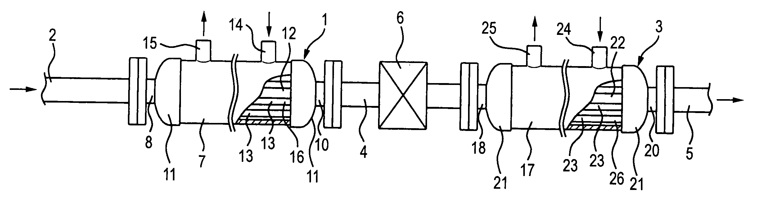
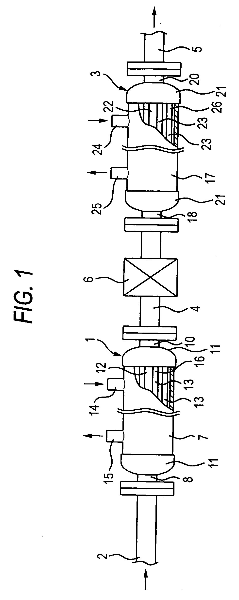
[0029] Hereinafter Embodiment 1 in which the EGR gas cooling apparatus of the present invention is used in an automobile will be described with reference to FIG. 1. A pre-EGR gas cooler 1 that performs the first step of cooling by introducing a high temperature EGR gas is coupled to the one end of the introduction pipe 2, in which a coupling hole(not shown) to the EGR pipe of the exhaust manifold side is installed. An post-EGR gas cooler 3, in which a medium temperature EGR gas cooled at the pre-EGR gas cooler 1 is introduced to cool down to the desired temperature, is coupled to the end of the pre-EGR gas cooler 1 in series through a second supplying pipe 4. The post-EGR gas cooler 3 is coupled to an outlet pipe 5 that is coupled to an intake manifold and passed therethrough at the other end, so that it is possible to supply a low temperature EGR gas, cooled to the desired temperature, to the intake manifold.

[0030] And, the EGR valve 6 is installed on the second sup...

Example

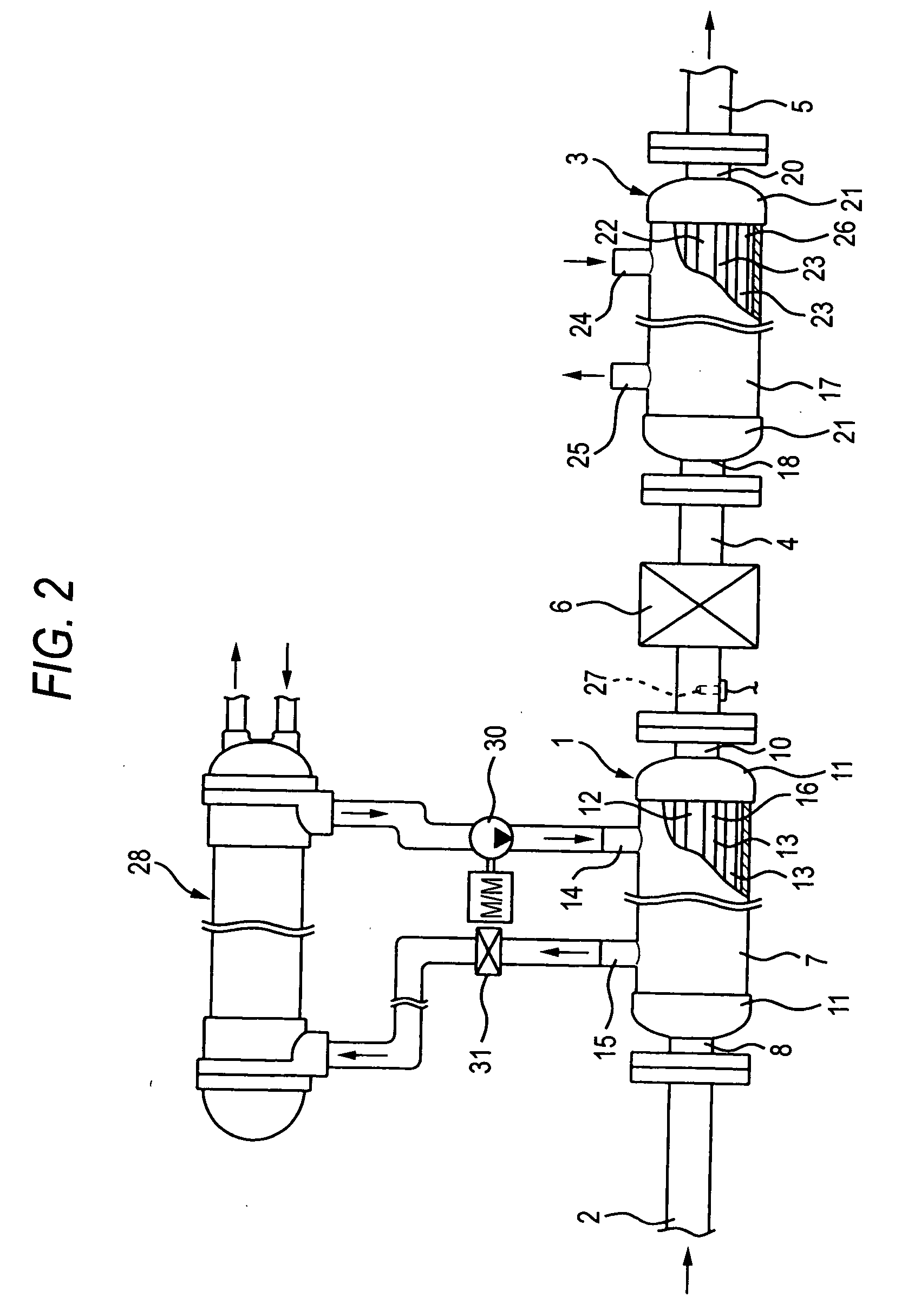
[0045] In a second embodiment as shown in drawing 2, similar to the first embodiment, the pre-EGR gas cooler 1 is coupled to the post-EGR gas cooler 3 in series, the EGR valve 6 is mounted in the second supplying pipe 4 connecting the coolers 1, 3 so that the amount of the EGR gas being introduced to the EGR gas cooling apparatus can be adjusted. In addition, in the second embodiment, a temperature sensor 27 is mounted between the pre-EGR gas cooler 1 and the EGR valve 6. And the temperature sensor measures the temperature of the medium temperature EGR gas cooled in the pre-EGR cooler, and monitors the temperature to maintain at 150° C. to 200° C.

[0046] Also, because the EGR gas having high temperature of 150° C. or more is introduced to the pre-EGR gas cooler 1 a thermal medium fluid of a high boiling point such as fluorine inert solvent having the boiling point of 150° C. or more is employed, in order not to make the refrigerant liquid boiled in the heat exchanging part 12. In ad...


PUM

PropertyMeasurementUnit
Temperatureaaaaaaaaaa
Boiling pointaaaaaaaaaa

Abstract

The pre-EGR gas cooler 1 for cooling the EGR gas introduced from the EGR pipe, and an post-EGR gas cooler for introducing the pre-EGR gas cooled in the EGR gas cooler 1 to cool it to a target cooling temperature are coupled in series, and an EGR valve is mounted for controlling the flow rate of the EGR gas between the pre-EGR gas cooler 1 and the post-EGR gas cooler 3. According to the invention, EGR gas cooling apparatus with improved durability can be obtained, and EGR valves with low product cost and high storage efficiency can be provided.

Description

BACKGROUND OF THE I MENTION [0001] The present invention relates to an EGR gas cooling apparatus for cooling EGR gas by heat-exchanging with a cooling-medium, and more particularly, to an EGR gas cooling apparatus having improved durability, in which an EGR valve is protected in high temperatures to improve the durability of apparatus, and the EGR valve provided in the EGR gas cooling apparatus controls a flow rate of the EGR gas supplied to an intake air. [0002] Conventionally, EGR systems, in which a part of exhaust gas is taken out of the exhaust gas system and returned to an intake system of the engine to be added to the mixture gas or the intake air with the control of the EGR valve, are used in engines for automobiles such as gasoline engines and diesel engines. This EGR system, particularly a high EGR-rate cooled EGR system for diesel engine has an EGR gas cooling apparatus that cools high temperature EGR gas by using a refrigerant liquid such as cooling water, cooling air, r...

Claims


Application Information

Patent Timeline
IPC IPC(8): F02M25/07F28D15/02F28F13/18F28F21/06
CPCF02M25/0701F02M25/0714F02M25/0731F02M25/0732F02M25/0737Y02T10/121F02M25/0754F28D15/0266F28D21/0003F28F13/18F28F21/062F02M25/0738F28F21/083F02M26/11F02M26/24F02M26/28F02M26/32F02M26/33F02M26/47F02M26/50
Inventor USUI, SHOICHIRO
Owner USUI KOKUSAI SANGYO KAISHA LTD
Why Eureka
Try Eureka