Vehicle upper body structure

a technology for vehicles and upper bodies, applied in the direction of roofs, wing accessories, transportation and packaging, etc., can solve the problem of difficult to strongly join the roof arch

Inactive Publication Date: 2005-11-17
HONDA MOTOR CO LTD
View PDF8 Cites 22 Cited by
  • Summary
  • Abstract
  • Description
  • Claims
  • Application Information

AI Technical Summary

Benefits of technology

[0010] According to the present invention, in the case in which the step part for arranging the slide rail is formed on the roof side rail, the pillar and roof arch are joined in the vicinity of the standing wall that c...

Problems solved by technology

However, it is difficult to strongly join the roof arch and the pillar onto the roof side rail in a vehicle having a slide door that slides as mentione...

Method used


Image

  • Vehicle upper body structure
  • Vehicle upper body structure
  • Vehicle upper body structure

Examples


Embodiment Construction

[0016] One embodiment of the vehicle upper body structure of the present invention is described hereunder, with reference to the drawings.

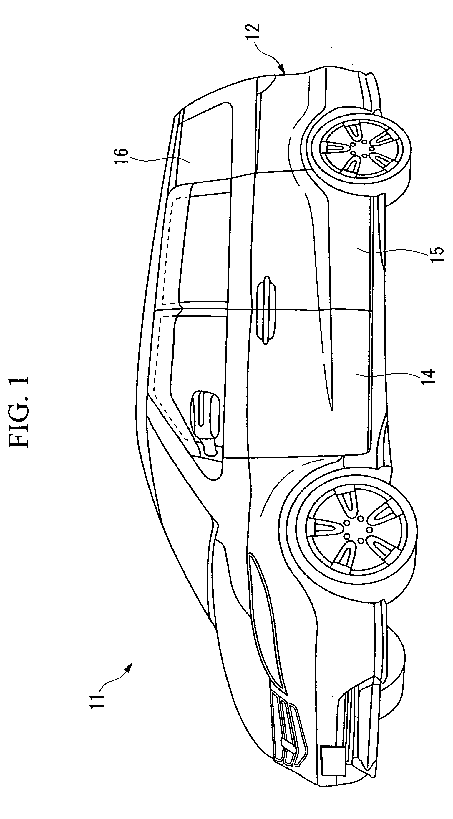
[0017] As shown in FIG. 1, a vehicle 11 has a front door 14 and a rear door 15 provided on the side part of a vehicle body 12. The rear door 15 is a sliding door that opens and closes by sliding in the lengthwise direction of the vehicle body. Moreover, a rear quarter window 16 is provided on the side part of the vehicle body 12 in a position to the rearward side of the closed rear door 15.

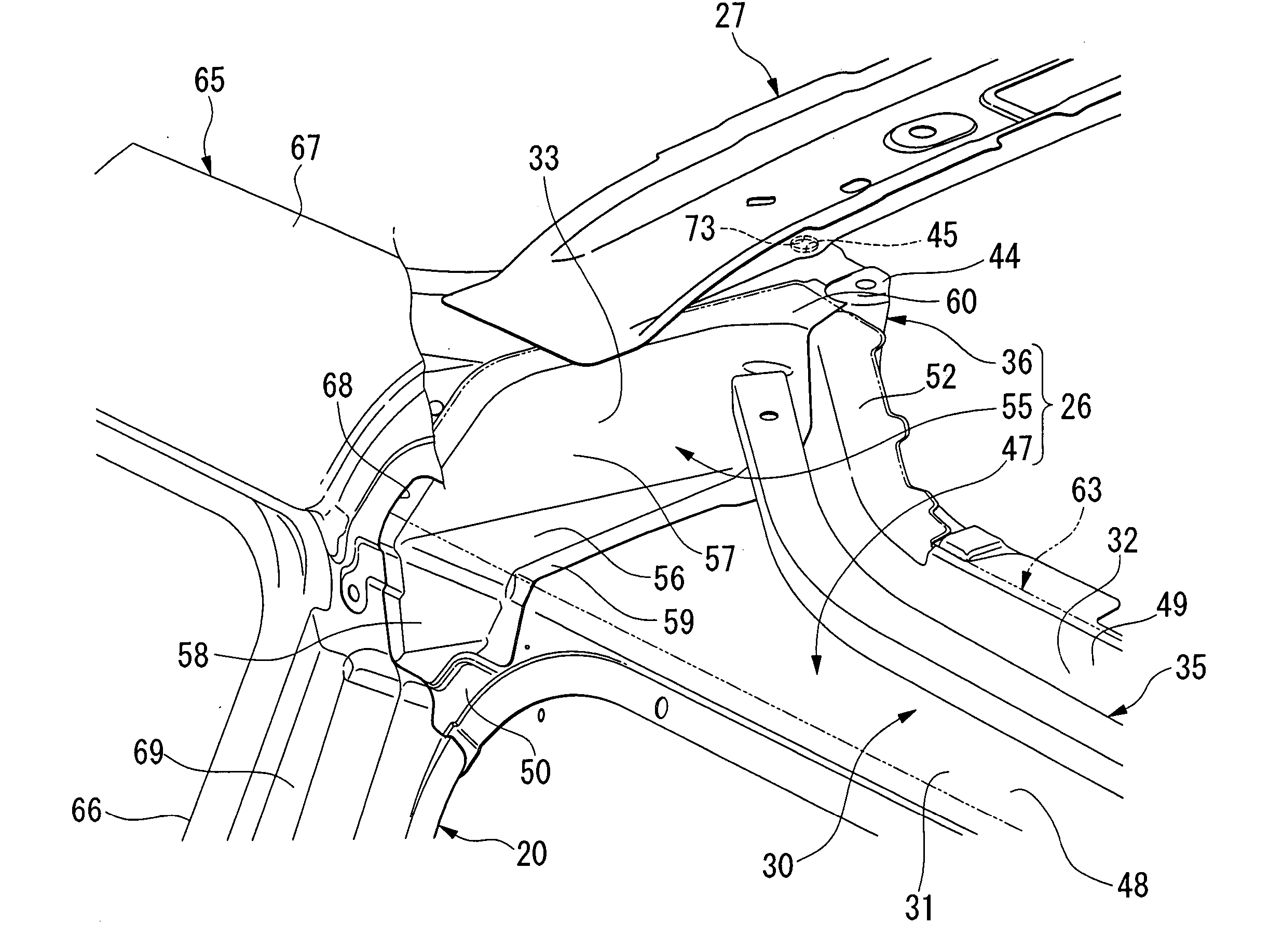
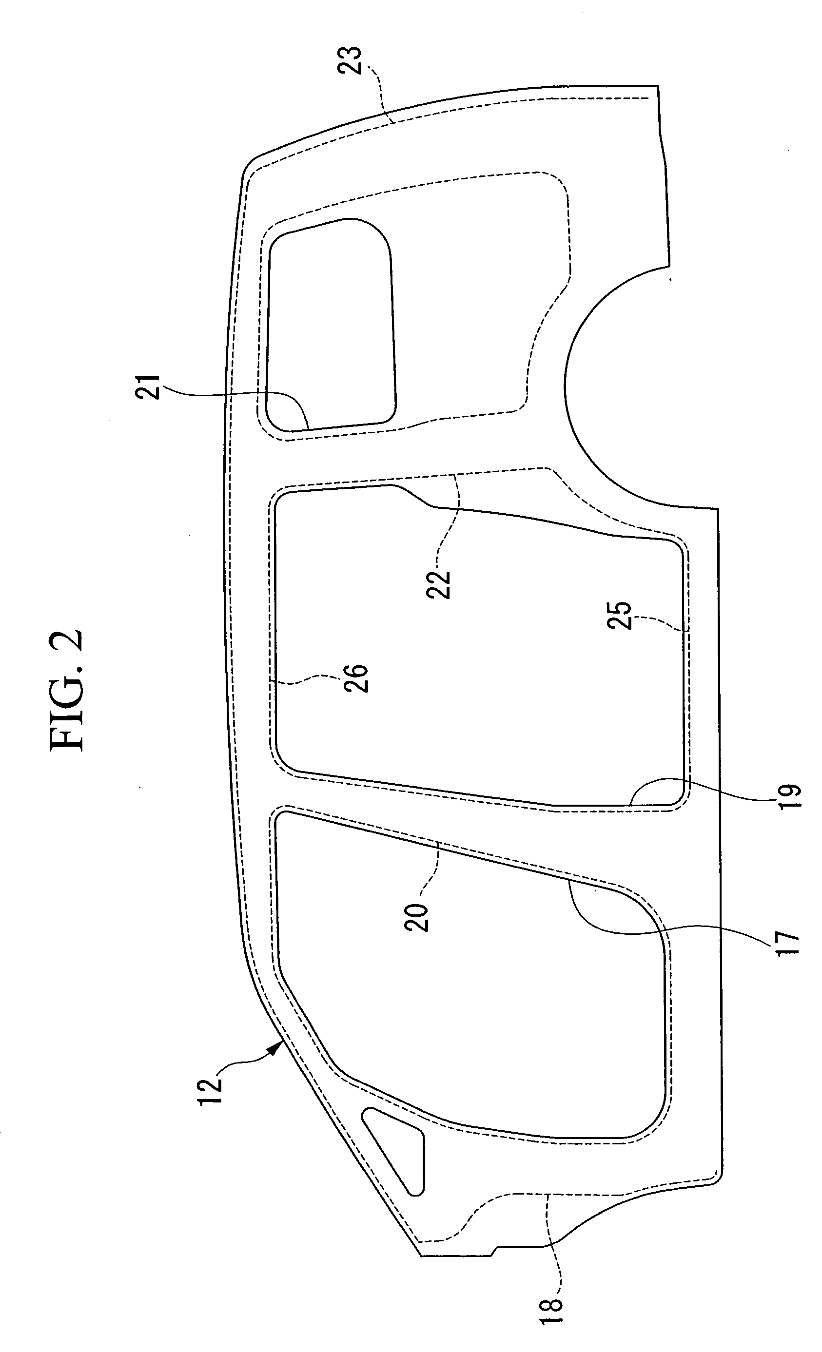
[0018] In FIG. 2 the skeletal structure of the side part of the vehicle body 12 is schematically shown. A front pillar 18 that constitutes the vehicle body frame extends in a substantially vertical direction on the vehicle body front side of an aperture part 17 on the side part of the vehicle body 12 that is opened and closed by the front door 14 shown in FIG. 1. The horizontal cross section of the front pillar 18 has a closed hollow structure. A center pillar...


PUM


Abstract

A vehicle upper body structure of the present invention includes: a step part for arranging a slide rail formed on a roof side rail; a pillar that is joined to the roof side rail in the vicinity of a standing wall that constitutes a front end part of the step part; and a roof arch that is joined to the roof side rail together with the pillar in the vicinity of the standing wall.

Description

BACKGROUND OF THE INVENTION [0001] 1. Field of the Invention [0002] The present invention relates to a vehicle upper body structure. [0003] Priority is claimed on Japanese Patent Application No. 2004-140940, filed May 11, 2004, the content of which is incorporated herein by reference. [0004] 2. Description of Related Art [0005] For a vehicle having a slide door that slides in the vehicle lengthwise direction, there is disclosed one in which there is provided on the upper side of the vehicle body a roof side rail that extends in the vehicle lengthwise direction, and a slide rail being supported by means of a bracket on the bottom side of this roof side rail (for example, see Japanese Unexamined Patent Application, First Publication No. 11-99961). Moreover, there is a vehicle in which a step part for arranging the slide rail is formed on the roof side rail, and the slide rail is supported by a roof side outer upper member, which is disposed so as to cover this step part from above. [0...

Claims


Application Information

Patent Timeline
IPC IPC(8): B62D25/04B62D25/06B62D25/07
CPCB62D25/06B62D25/04
Inventor TOMOZAWA, KOSAKU
Owner HONDA MOTOR CO LTD
Why Eureka
Try Eureka