Dual stacked connector

a technology of double stacked connectors and connectors, applied in the direction of coupling device connections, lighting and heating apparatus, instruments, etc., can solve the problem that the connector cannot be practically inserted into a shielding cage by

Active Publication Date: 2005-11-17
MOLEX INC
View PDF36 Cites 54 Cited by
  • Summary
  • Abstract
  • Description
  • Claims
  • Application Information

AI Technical Summary

Benefits of technology

[0007] Accordingly, it is a principal object of the present invention to provide a small form factor circuit board connector in a stacked configuration having engagement faces thereof spaced vertically apart.

Problems solved by technology

A problem arises with these type of connectors because the terminals of the connector are usually stitched in from the rear of the connector.
When a dual connector of a stacked arrangement, i.e., one which is intended to mate with two electronic modules in a vertically spaced arrangement, is desired, such a connector cannot be practically inserted into a shielding cage by way of a bottom opening because of the intervening horizontal wall of the shielding cage.

Method used


Image

  • Dual stacked connector
  • Dual stacked connector
  • Dual stacked connector

Examples


second embodiment

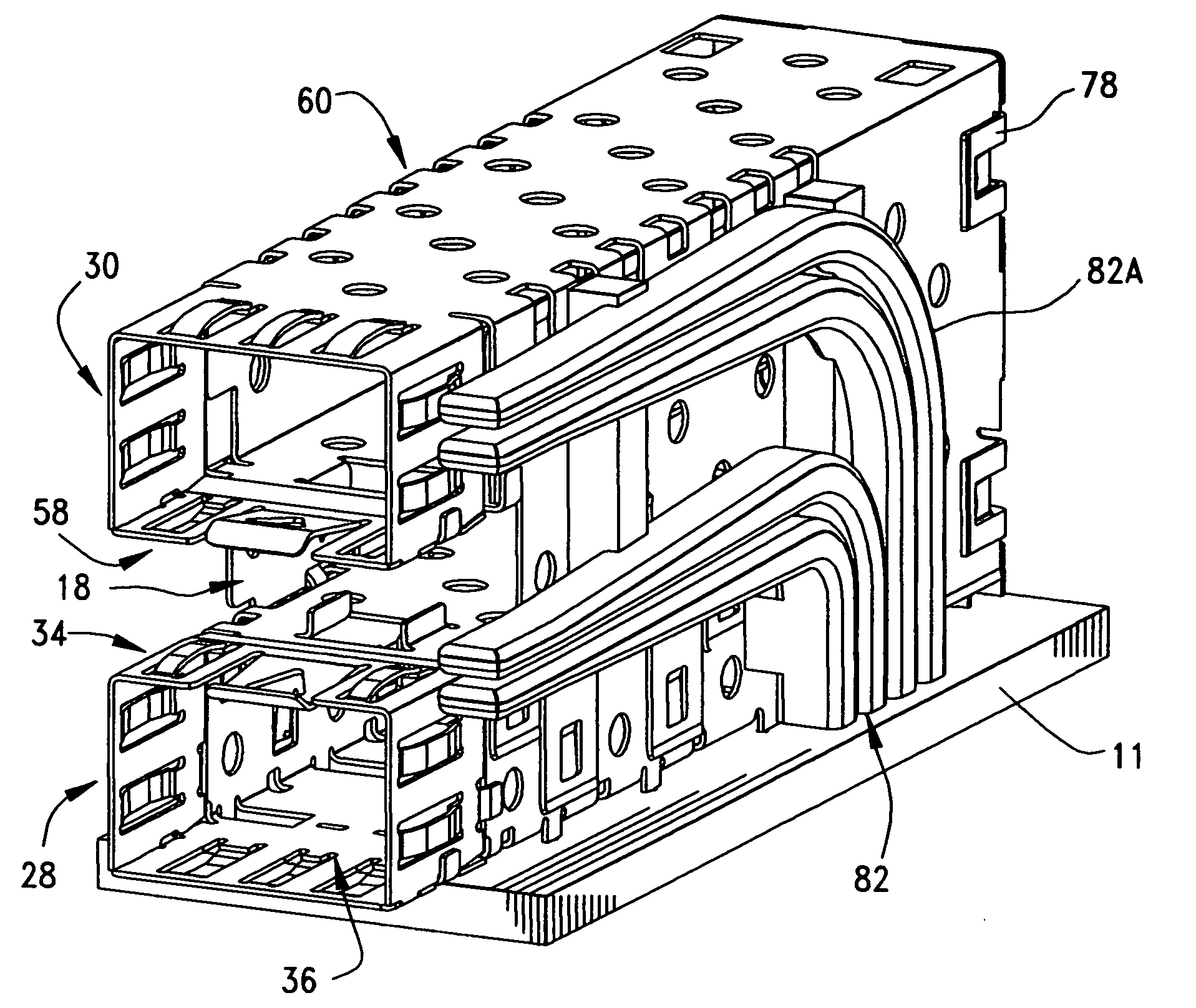
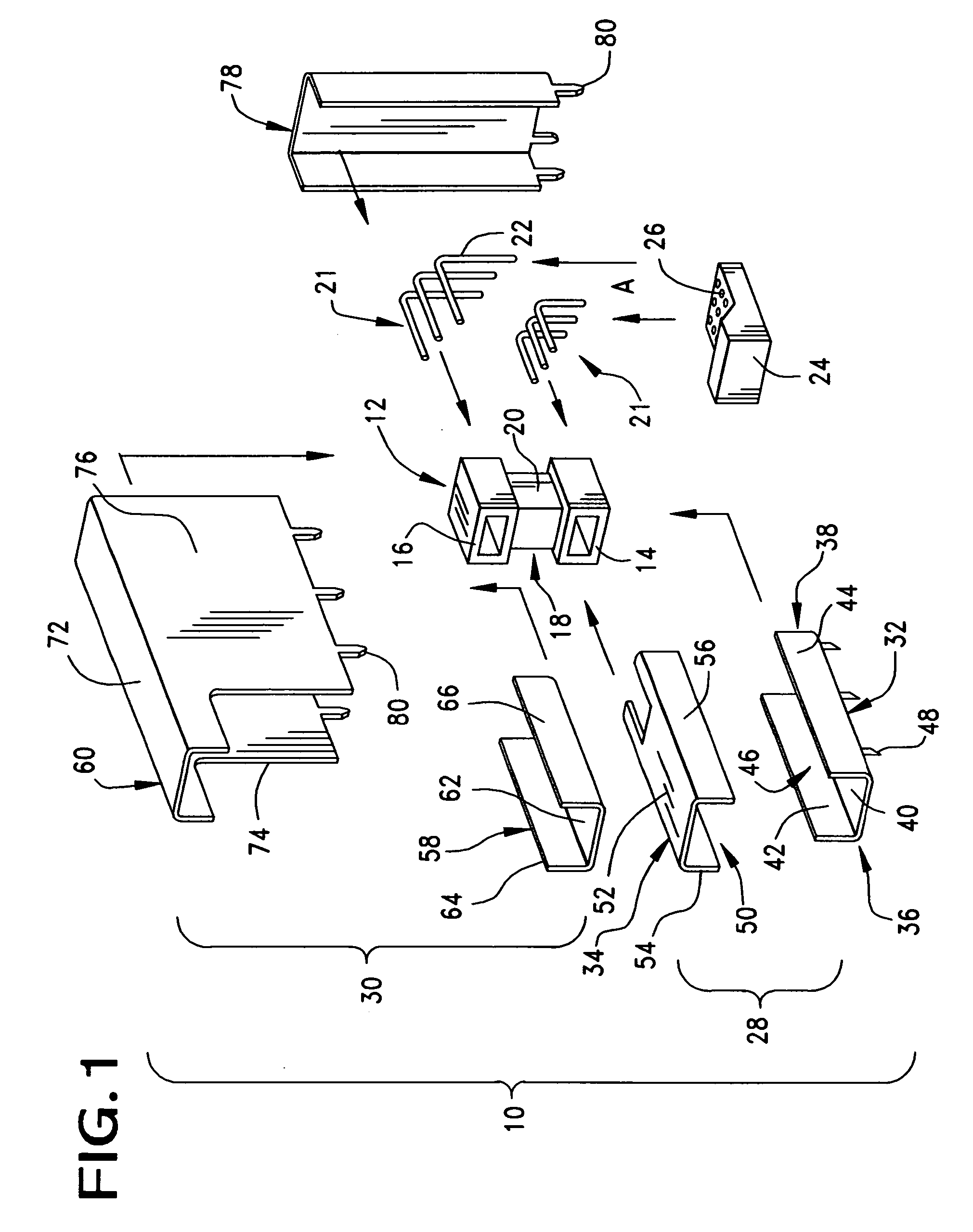
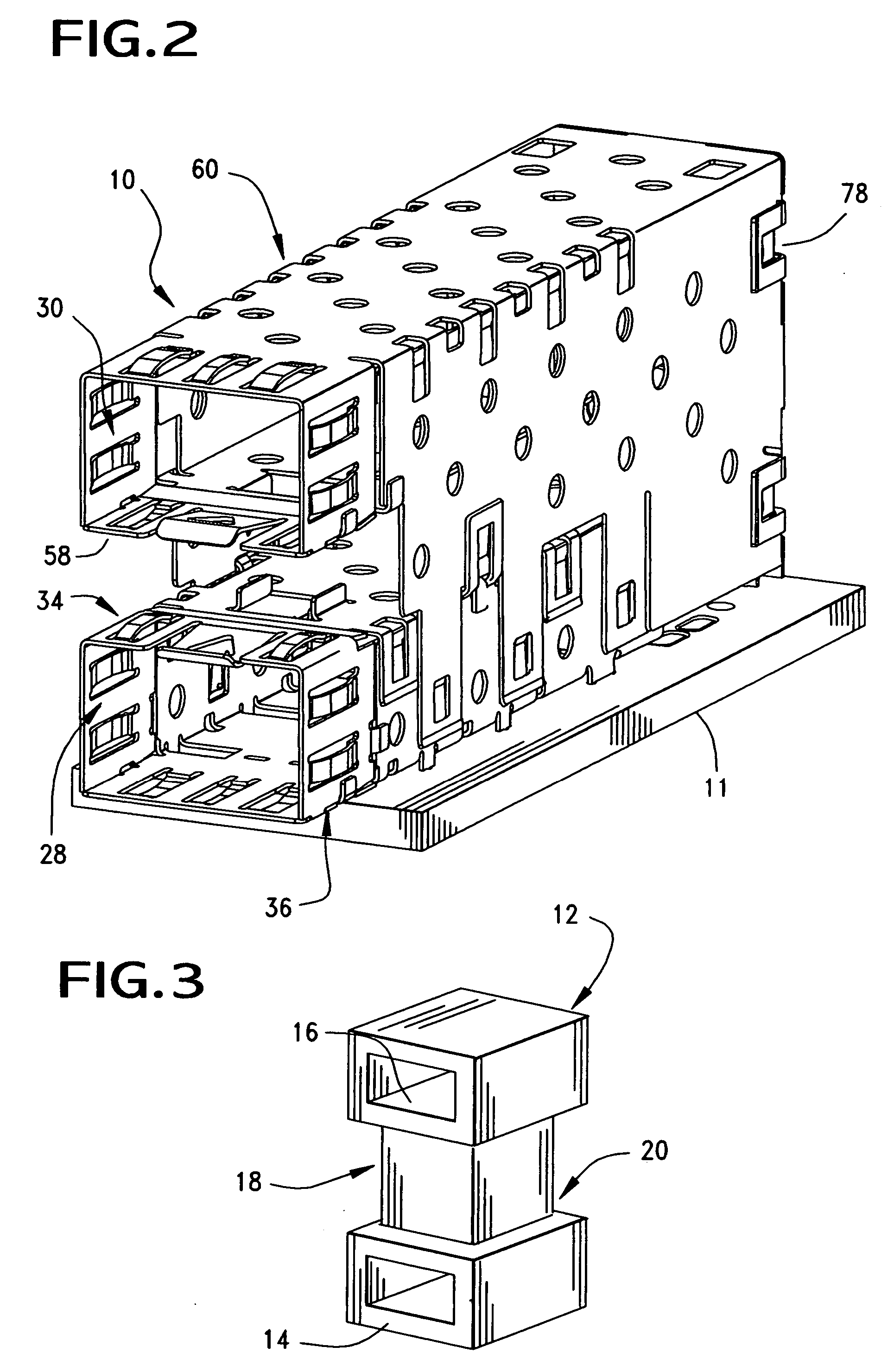
[0084] Assembly of connector assembly 12 will now be described with reference to FIGS. 1, 2, 7 and 8. In a first step, the terminals are press-fit into connector housing 12. Terminal tail portions 22 are then inserted into tail aligner holes 26 and tail aligner 24 is secured to connector housing 12, thereby securing tail portions 22 with respect to housing 12. In this embodiment, the lower cage assembly 28 is then secured to the connector lower housing port 14, and the base portion 58 of the upper cage assembly 30 is then attached to the connector upper housing port 16. The light pipe assembly 82b is then press-fit into housing recess 20 and the housing cavity 18. Upper cage assembly cover component 60 is then attached to upper cage assembly base component 60, thereby enclosing light pipe assembly 82b within side walls of upper cover component 60. The spacing between the upper and lower cage assemblies 30, 28 defines a cavity that extends lengthwise of the connector assembly and thi...

embodiment 400

[0095]FIGS. 27 and 28 illustrate an embodiment 400 in which the light pipe assembly 401 is integrally formed as a single piece, such as by injection molding or any suitable process. In FIG. 28 the light pipe assembly 401 has two pairs of light pipes 403 associated which are interconnected together by support members 405 to form a lattice-like structure. The support members 405 are shown interconnecting together both the vertical and horizontal portions of the light pipes. Another set of support members 407 may interconnect the horizontal portions and may include engagement members 409 formed therewith, which are received within corresponding openings 412 disposed in the front face 413 of the associated connector component 420. The forwardmost support member 405 may also include an engagement member, shown as a hook member 423 that engages the shoulder 430 of an end cap 431. Once again in this embodiment, the light pipe assembly 401 is supported entirely along the front face 413 of t...


PUM

PropertyMeasurementUnit
L-shapeaaaaaaaaaa
anglesaaaaaaaaaa
sizeaaaaaaaaaa

Abstract

A small size connector has an insulative housing and two edge card-receiving slots disposed in a stacked arrangement with in the connector housing. Each slot receives an edge card of an electronic module therein. The slots support conductive terminals that extend from a plurality of individual terminal assemblies. The terminal assemblies include clip members that engage an opposing shoulder formed on the interior of the connector housing. The front face of the connector is provided with various engagement openings that receive engagement members of light pipe assemblies and shielding assemblies, so that when assembled, the connector, shield, terminal assemblies and light pipes all act as a single, integrated component.

Description

REFERENCE TO RELATED APPLICATIONS [0001] This application claims priority of prior U.S. Provisional Patent Applications Nos. 60 / 571,375, filed May 14, 2004 and 60 / 584,420, filed Jun. 30, 2004 and 06 / 584,421, also filed Jun. 30, 2004. BACKGROUND OF THE INVENTION [0002] This invention relates to electrical connector assemblies and, more particularly, to an small sized electrical connectors having a stacked arrangement. [0003] Electrical connectors adapted for mounting to printed circuit boards are known in the art and are commonly used for connection between two electrical communication devices. In order to ensure that a proper connection has been made and therefore a link is created between the electrical communication devices, indicators may be incorporated into circuits on the printed circuit board. These indicators are typically light emitting diodes (LEDs) which are turned on when a circuit is completed between the mating connectors and the communication devices. Additionally LED...

Claims


Application Information

Patent Timeline
Patent Type & Authority Applications(United States)
IPC IPC(8): F21V5/00F21V7/04F21V8/00F21V17/00G02B6/38H01R12/00H01R13/648H01R13/658H01R13/717
CPCG02B6/0001G02B6/0008H01R13/65802H01R13/717H01R13/7172Y10T29/49208H01R23/6873H01R13/658H01R24/60H01R13/518H01R13/7175G02B6/0096H01R12/724H01R13/6582H01R13/6587H01R13/659H01R13/6594H01R12/00H01R12/716
Inventor LONG, JERRY A.
Owner MOLEX INC
Why Eureka
Try Eureka