Spare tire usage detection

a technology for detecting the usage of spare tires and tires, which is applied in the direction of tyre measurement, vehicle components, selection arrangements, etc., can solve the problem of no longer current information stored in the central electronics uni

Active Publication Date: 2005-11-24
GM GLOBAL TECH OPERATIONS LLC
View PDF7 Cites 72 Cited by
  • Summary
  • Abstract
  • Description
  • Claims
  • Application Information

AI Technical Summary

Problems solved by technology

A weakness of this arrangement is that when an unexpected tire change is made (e.g., when a flat occurs) the information stored in the central electronics unit is no longer current.

Method used


Image

  • Spare tire usage detection
  • Spare tire usage detection
  • Spare tire usage detection

Examples


Embodiment Construction

[0012] The following detailed description is merely exemplary in nature and is not intended to limit the invention or the application and uses of the invention. Furthermore, there is no intention to be bound by any expressed or implied theory presented in the preceding technical field, background, brief summary or the following detailed description.

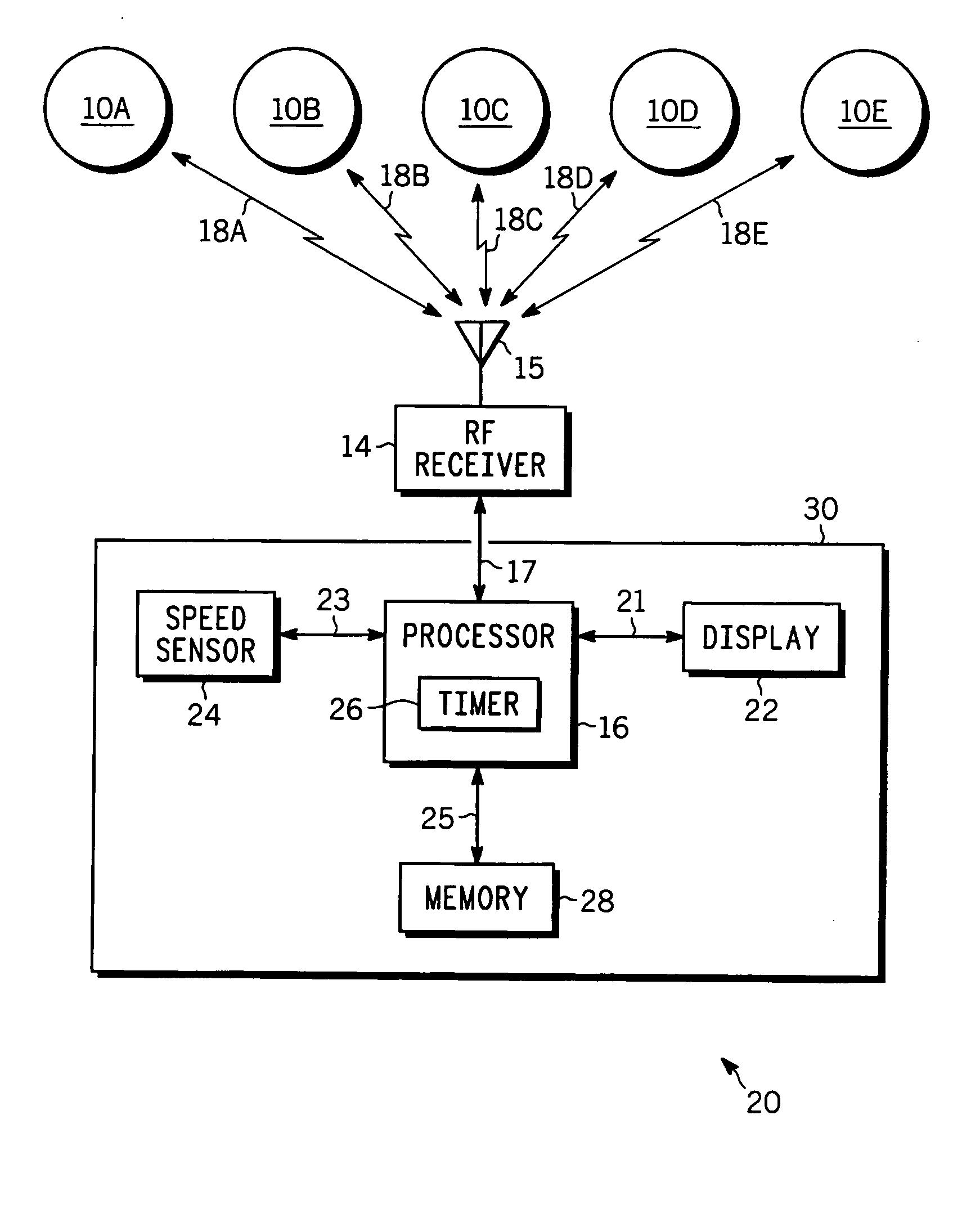
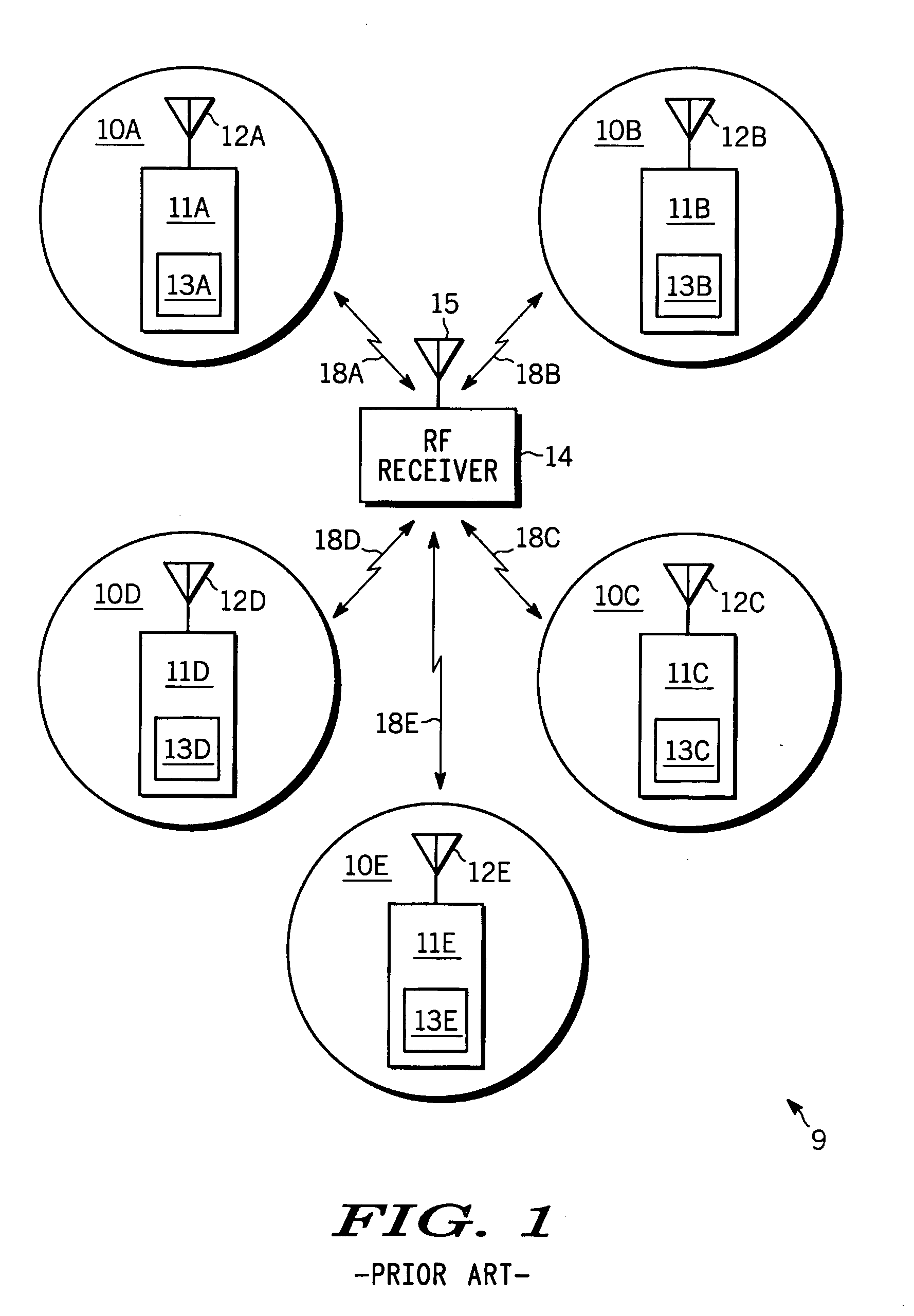
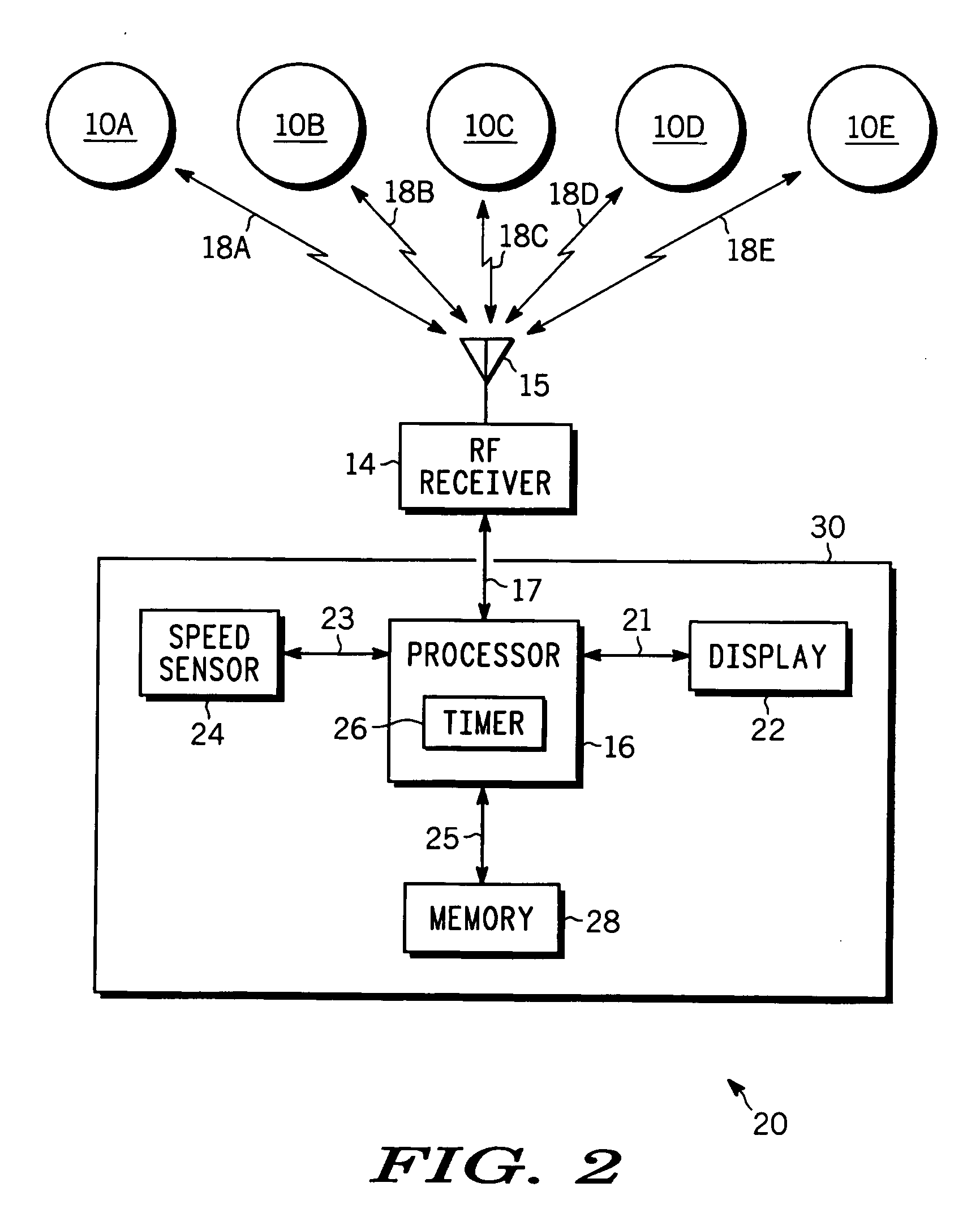
[0013] As used herein, the word “wheel” whether singular or plural is intended to be inclusive of the tire mounted thereon. For example, reference to data from a particular wheel is understood to include the desired information about the tire mounted thereon. Further the words “receiver” and “transmitter” or “sender” are not intended to be limited merely to signal incoming and outgoing functions, respectively, but are intended to include the meaning of “transceiver” that is, be capable of two-way wireless communication as the need arises. For convenience of explanation, it is assumed for purposes of the present invention that the learnin...


PUM


Abstract

Methods and apparatus are provided for detecting when a spare wheel (SP) is used to replace a previously rolling wheel on a vehicle, where each wheel can transmit wheel ID and motion status signals. The apparatus comprises a receiver, a memory for storing information relating wheel ID and location, a processor coupled to the receiver and memory for analyzing the wheel signals to determine if the SP is rolling, and a timer coupled to the processor that measures how long the SP has been rolling. When the SP has been rolling for predetermined time T, the processor looks at the motion status signals from remaining wheels to determine which is stopped, and then modifies the information stored in the memory to associate the SP ID with the wheel location formerly occupied by the now stopped wheel and associate the stopped-wheel ID with the storage location for the spare.

Description

TECHNICAL FIELD [0001] The present invention generally relates to systems and methods for monitoring wheel and tire usage on vehicles, and more particularly, automatically determining whether a vehicle spare tire has been put into active use on the vehicle. BACKGROUND [0002] It is known to provide RF sending units on vehicle wheels that provide information to a central radio receiver and processor on the vehicle about the status of the wheel, e.g., the wheel identity number (ID), the wheel location, whether it is rolling or stationary, wheel temperature, tire pressure, and so forth. Such systems are described for example in U.S. Pat. No. 5,109,213 to Williams; U.S. Pat. No. 6,441,728 B1 to Dixit et al, U.S. Pat. No. 6,4876,773 B1 to Baille et al, U.S. Pat. No. 6,518,876 B1 to Marguet et al and U.S. Pat. No. 6,580,365 B2 to Starkey. [0003]FIG. 1 is a simplified schematic diagram of prior art system 9 comprising five vehicles wheels 10A-10E interacting with on-board data receiver 14. ...

Claims


Application Information

Patent Timeline
Patent Type & Authority Applications(United States)
IPC IPC(8): B60C23/00B60C23/04
CPCB60C23/0416
Inventor UTTER, THOMAS E.WALTERS, MARK A.FRAKES, RYAN M.TU, THOMAS H.BUCK, M. SCOTTOSINSKI, DAVID A.
Owner GM GLOBAL TECH OPERATIONS LLC
Why Eureka
Try Eureka