Plasma display apparatus and driving method thereof

a technology of display apparatus and driving method, which is applied in the direction of instruments, computing, electric digital data processing, etc., can solve the problems of different brightness on the left side of the screen and the brightness on the right side thereof, complicated circuit construction, and heat generated in each electrode driving uni

Inactive Publication Date: 2005-11-24
LG ELECTRONICS INC
View PDF7 Cites 6 Cited by
  • Summary
  • Abstract
  • Description
  • Claims
  • Application Information

AI Technical Summary

Benefits of technology

[0025] Accordingly, the present invention has been made in view of the above problems occurring in the prior art, and it is an object of the present invention to provide a plasma display apparatus and driving method thereof, wherein a difference in the brightness in the right and left sides of a screen is prevented from occurring due to EMI and a voltage drop, which are generated upon driving, by improving a driving circuit that operates in an address period and a sustain period.

Problems solved by technology

Further, since the electrode driving units are located at both sides, the construction of the circuit is complicated.
Further, there are many problems in that heat generated in each electrode driving unit affects other electrode driving units, etc.
Accordingly, there are problems in that the brightness on the left side of a screen and the brightness on the right side thereof are different, and the like.

Method used


Image

  • Plasma display apparatus and driving method thereof
  • Plasma display apparatus and driving method thereof
  • Plasma display apparatus and driving method thereof

Examples


Embodiment Construction

[0047] The present invention will now be described in detail in connection with preferred embodiments with reference to the accompanying drawings.

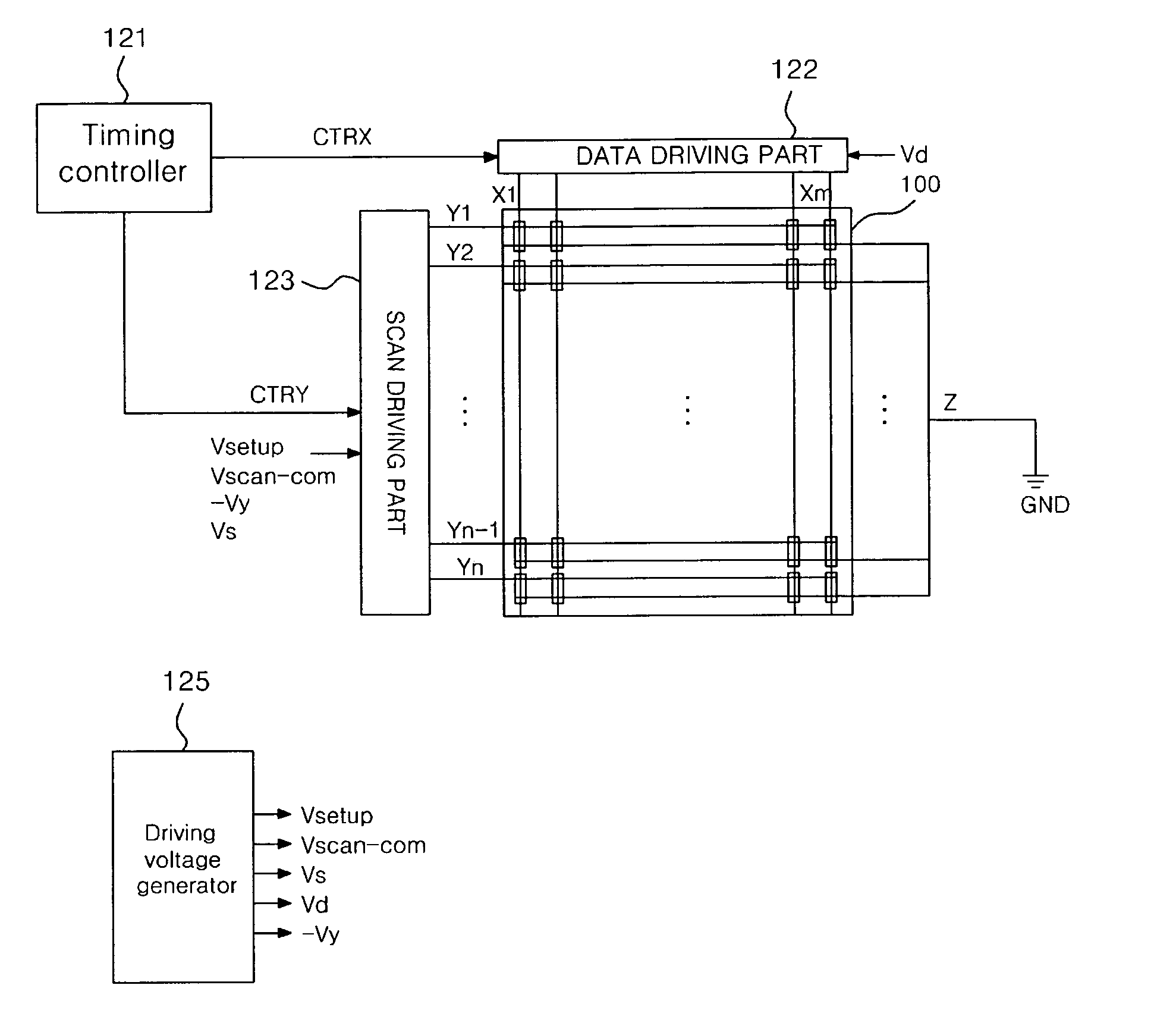
[0048]FIG. 4 is a block diagram showing the construction of a plasma display apparatus according to the present invention.

[0049] Referring to FIG. 4, the plasma display apparatus according to the present invention includes a PDP 100, a data driving unit 122 for supplying data to address electrodes X1 to Xm formed in a lower substrate (not shown) of the PDP 100, a scan driving unit 123 for driving scan electrodes Y1 to Yn, a timing control unit 121 for controlling the data driving unit 122 and the scan driving unit 123 when the PDP is driven, and a driving voltage generator 124 for supplying driving voltages necessary for the respective driving units 122 and 123. That is, the plasma display apparatus according to the present invention does not include a sustain driving unit for driving a sustain electrode Z, and the sustain electrode Z is...


PUM


Abstract

The present invention relates to a plasma display apparatus and driving method thereof. According to the present invention, the plasma display apparatus includes a plasma display panel in which scan electrodes and sustain electrodes are formed, and a scan driving unit that applies a scan voltage and a sustain voltage whose absolute values are the same to the scan electrodes, wherein the sustain electrodes are kept to the ground.

Description

CROSS-REFERENCES TO RELATED APPLICATIONS [0001] This Nonprovisional application claims priority under 35 U.S.C. § 119(a) on Patent Application No. 10-2004-0035570 filed in Korea on May 19, 2004 the entire contents of which are hereby incorporated by reference. BACKGROUND OF THE INVENTION [0002] 1. Field of the Invention [0003] The present invention relates to a plasma display apparatus and driving method thereof. [0004] 2. Background of the Related Art [0005] A plasma display panel (hereinafter, referred to as “PDP”) is adapted to display an image including characters or graphics by light-emitting phosphors by ultraviolet of 147 nm generating upon discharging of inert mixed gas such as He+Xe or Ne+Xe. [0006]FIG. 1 is a perspective view illustrating the construction of a three-electrode AC surface discharge type PDP having a discharge cell structure arranged in the form of matrix in the prior art. [0007] Referring to FIG. 1, the three-electrode AC surface discharge type PDP 100 inclu...

Claims


Application Information

Patent Timeline
Patent Type & Authority Applications(United States)
IPC IPC(8): G09G3/28G09G3/20G09G3/288G09G3/291G09G3/292G09G3/293G09G3/294G09G3/296G09G3/298
CPCG09G3/293G09G3/294G09G2330/06G09G2310/0267G09G2300/0426G09G3/296
Inventor MOON, SEONG HAK
Owner LG ELECTRONICS INC
Why Eureka
Try Eureka