Foot sensor apparatus, method & system

a sensor and foot technology, applied in the field of remote sensing, can solve the problems of inconvenient and unsightly wire connection of devices to measurement apparatuses, and cannot be readily used with existing footwear of athletes,

Inactive Publication Date: 2005-11-24
KINETEKS CORP
View PDF18 Cites 191 Cited by
  • Summary
  • Abstract
  • Description
  • Claims
  • Application Information

AI Technical Summary

Problems solved by technology

A number of electronic devices are known for measuring a force caused by a foot, for example, however these devices have various drawbacks.
Some devices require custom-built footwear to be constructed in order to measure force caused by the foot, and cannot readily be used with an athlete's existing footwear.
Many devices require an inconvenient and unsightly wire connection to a measurement apparatus, which is either obtrusively worn on the body or which must be carried along to a new location every time the athlete moves.

Method used


Image

  • Foot sensor apparatus, method & system
  • Foot sensor apparatus, method & system
  • Foot sensor apparatus, method & system

Examples


second embodiment

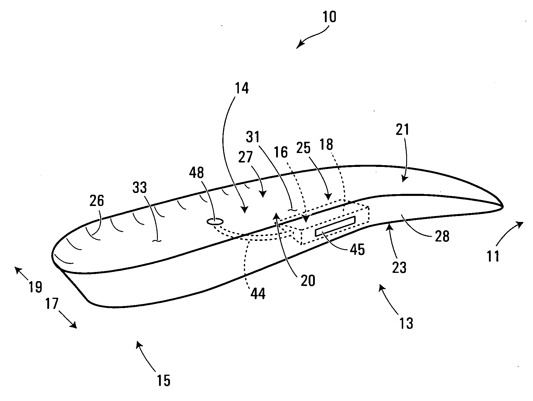
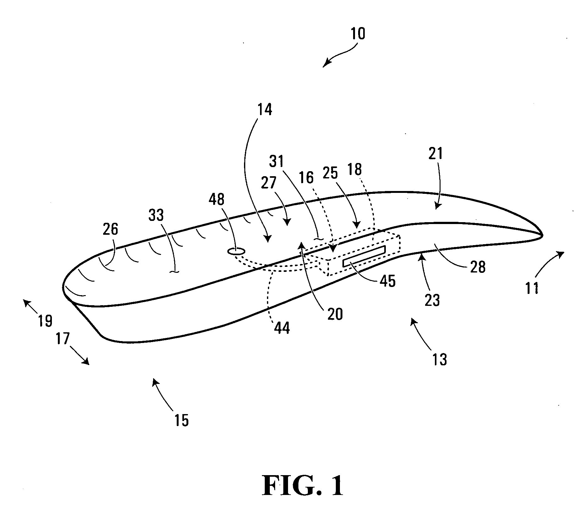
[0056] Referring now to FIGS. 4 and 5, an apparatus for use in sensing a physical condition caused by a foot according to a second embodiment of the invention is shown generally at 12. The apparatus 12 includes the foot support body 14 previously described, however in this embodiment the body 14 is placed with its bottom portion 23 on an underlay 24 and an overlay 22 is placed on the top portion 21 of the body 14. Effectively, the body 14 is placed in between the overlay 22 and the underlay 24. As previously described, the body 14 has a transmitter unit holder 16 including a cavity 18 (shown in broken outline in FIG. 1) operable to hold a transmitter unit (not shown in FIG. 4, but referred to in FIGS. 6, 7 and 9 by reference character 102). In this embodiment, the apparatus 12 may be affixed inside footwear permanently, or it may be removably insertable into the footwear.

[0057] The overlay 22 extends into a forefoot region 11 of the footwear (not shown). In this embodiment, the ove...

third embodiment

[0070] Referring now to FIG. 10, an apparatus for use in sensing a physical condition caused by a foot according to a third embodiment of the invention is shown generally at 70. The apparatus 70 is similar to the apparatus shown in the embodiments described previously, however, in this embodiment, the electronic circuitry and condition sensors may be embedded within an integrated flexible circuit layer 140, which may be manufactured using a synthetic film substrate such as Mylar®, for example. Effectively, the flexible circuit layer 140 performs substantially the same function as the circuit board 110 previously described, thus it may be understood for purposes of this description as a flexible type of circuit board.

[0071]FIG. 10 illustrates that in this embodiment the flexible circuit layer 140 is embedded between an overlay 222 and an underlay 224 in order to protect the circuit layer 140 from damage and to enable the apparatus 70 to comfortably support a foot. The overlay 222 an...


PUM

PropertyMeasurementUnit
physical conditionaaaaaaaaaa
physicalaaaaaaaaaa
radio frequencyaaaaaaaaaa

Abstract

A method, apparatus and system for communicating to a remote location a representation of a physical condition caused by a foot. The method involves communicating to a transmitter unit at least partially held within a cavity in a foot support operable to be inserted into footwear, a condition signal representing the physical condition sensed by a condition sensor; and transmitting from the transmitter unit a radio frequency (RF) signal representing the condition signal, for reception by a receiver unit spaced apart from the transmitter unit. An apparatus and system using the method are also disclosed.

Description

BACKGROUND OF THE INVENTION [0001] 1. Field of Invention [0002] The present invention relates to remote sensing, and more particularly, to an apparatus, method and system for communicating to a remote location a representation of a physical condition caused by a foot. [0003] 2. Description of Related Art [0004] In many sports it is Useful to measure and analyse physical conditions caused by a foot in order to improve sports performance. In particular, an analysis of how weight is shifted to different parts of a foot or to the other foot may help to optimize the performance of an athlete in many sports such as golf or baseball. [0005] A number of electronic devices are known for measuring a force caused by a foot, for example, however these devices have various drawbacks. Some devices require custom-built footwear to be constructed in order to measure force caused by the foot, and cannot readily be used with an athlete's existing footwear. Many devices require an inconvenient and uns...

Claims


Application Information

Patent Timeline
Patent Type & Authority Applications(United States)
IPC IPC(8): A61B5/103A61B5/117A61B5/22G01L1/00G08C17/02
CPCA43B3/0005A61B5/6807A61B5/1038A43B3/34
Inventor COLLINGS, TIMOTHY DAVIDYOUNKER, JOANNE ROSALIE
Owner KINETEKS CORP
Why Eureka
Try Eureka