Selectively incrementally actuated linear eddy current braking system

Active Publication Date: 2005-12-01
VELOCITY MAGNETICS
View PDF24 Cites 44 Cited by
  • Summary
  • Abstract
  • Description
  • Claims
  • Application Information

AI Technical Summary

Benefits of technology

[0009] It is a further object of the invention to provide an electrodynamic brake that do

Problems solved by technology

But no known system provides for the precise shifting of the modules to selected phase angles to provide the application of a number of selected braking forces.
In most instances, achieving the desired incremental application of brake force is not possible due to the high diff

Method used


Image

  • Selectively incrementally actuated linear eddy current braking system
  • Selectively incrementally actuated linear eddy current braking system
  • Selectively incrementally actuated linear eddy current braking system

Examples


Embodiment Construction

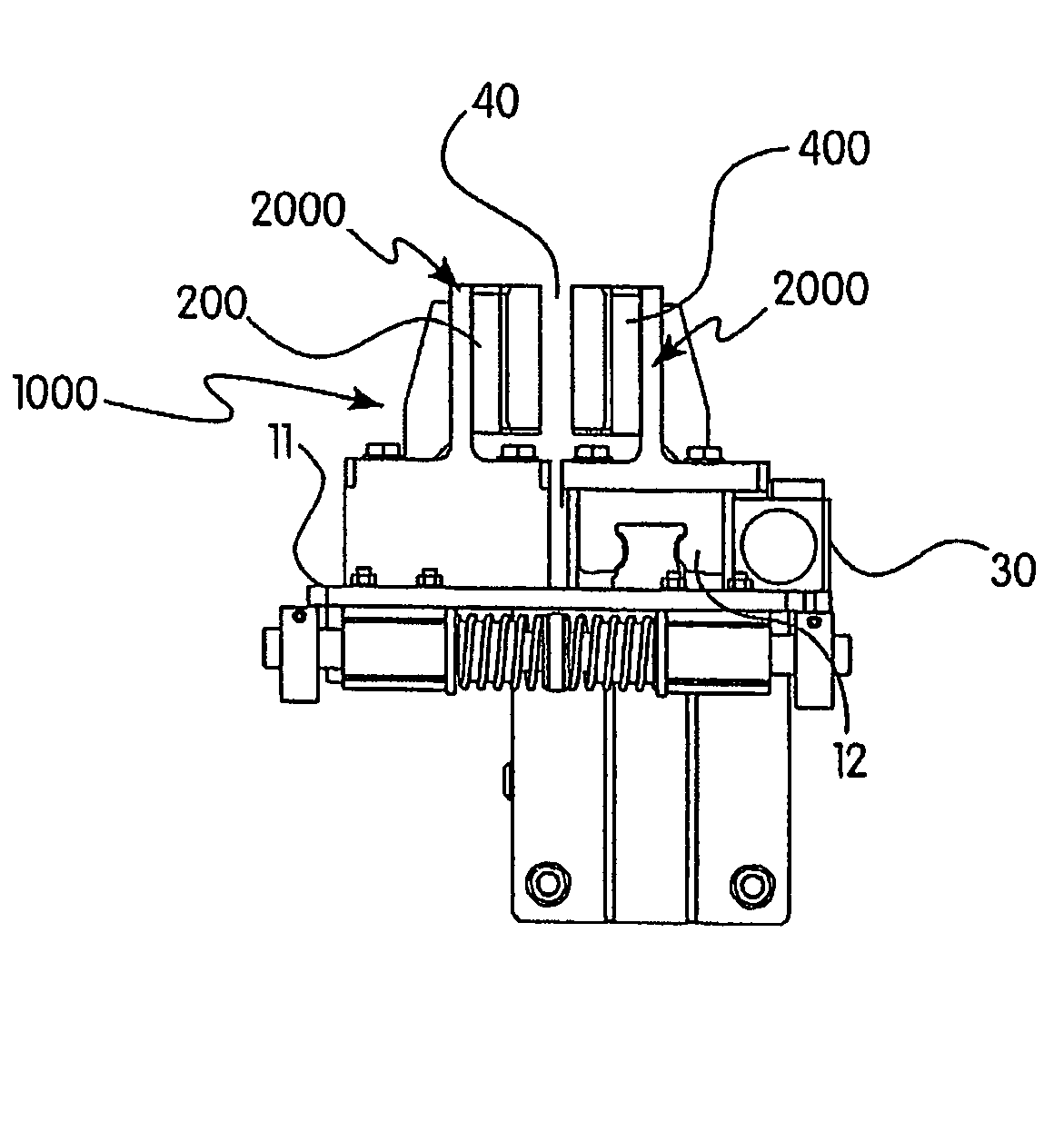
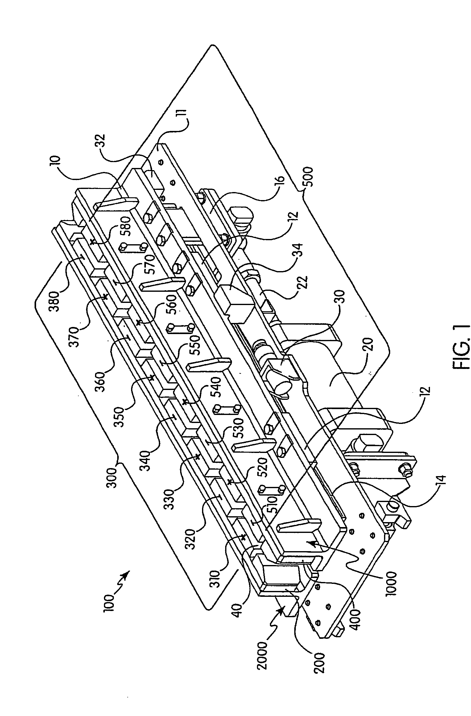
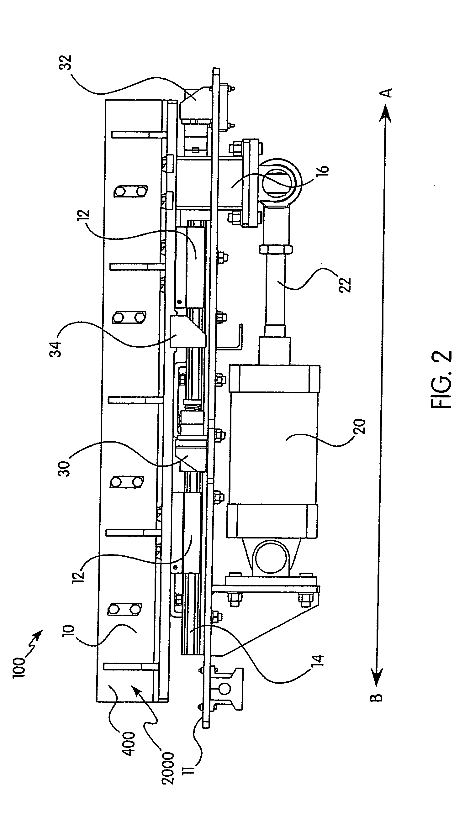
[0018] The inventive system 100 is intended to operate in conjunction with a conventional type synchronous linear electrical machine operating as a motor or an electrodynamic brake. An example of such a synchronous linear electrical machine operating as a motor or an electrodynamic brake preferably comprises primary members 300, 500 comprising arrays of at least two permanent magnets 310-380, 510-580 of alternating polarity. The magnets are preferably attached to back plates 200, 400 and along with backplate and plates 10 comprise respective modules 1000, 2000. Preferably, a synchronous linear secondary stator member (not shown) accompanies the primary members to provide the synchronous linear electrical machine operating as a motor or an electrodynamic brake. A stator member can be mounted on the bottom of any incoming vehicle a fin-like protrusion that passes through the air gap 40 (shown in FIG. 3) between primary members 300, 500 of modules 1000, 2000. When the stator member and...


PUM


Abstract

The invention is an incrementally actuated eddy current braking system. The system comprises first and second primary members, which further comprise arrays of permanent magnets arranged in alternating polarity. The respective magnets of the arrays face one another. A means for incremental displacement is drivingly connected to at least one of the primary members enabling the movement of said members relative to one another.

Description

CLAIM OF PRIORITY [0001] This application claims priority of U.S. Provisional Application No. 60 / 575,431 filed on May 28, 2004.FIELD OF THE INVENTION [0002] This invention relates to a linear synchronous magnetic motor utilized primarily for braking. In particular, this invention relates to a linear synchronous magnetic motor utilized for braking that can be incrementally actuated to allow for the application of the variable braking force. BACKGROUND OF THE INVENTION [0003] It is known in the art to provide a linear synchronous magnetic motor as an electrodynamic brake. Such electrodynamic brakes are activated when the modules of the brake having permanent magnets of alternating polarity face one another, wherein each permanent magnet in each array faces and opposes a magnet of opposite polarity. The brakes can be deactivated by displacing one of the modules forward or backward 180 electrical degrees, which causes the magnetic field to diminish to a negligible level. [0004] At prese...

Claims


Application Information

Patent Timeline
IPC IPC(8): B60T8/86B61H7/08H02K49/04
CPCB60L7/28B61H7/083F16D2121/24F16D2129/065F16D63/002
Inventor MARZANO, DOMENIC P.GUSTASON, MICHAEL
Owner VELOCITY MAGNETICS
Why Eureka
Try Eureka