Method and apparatus for keeping track of virtual LAN topology in network of nodes

a topology and network technology, applied in the field of ethernet networks, can solve problems such as inutility of techniques

Inactive Publication Date: 2005-12-01
FUJITSU LTD
View PDF13 Cites 146 Cited by
  • Summary
  • Abstract
  • Description
  • Claims
  • Application Information

AI Technical Summary

Problems solved by technology

Therefore, these techniques are not useful in conditions where reconfiguration occurs with a node that is not exactly identifiable among the nodes constituting a virtual LAN like the above event.

Method used


Image

  • Method and apparatus for keeping track of virtual LAN topology in network of nodes
  • Method and apparatus for keeping track of virtual LAN topology in network of nodes
  • Method and apparatus for keeping track of virtual LAN topology in network of nodes

Examples


first embodiment

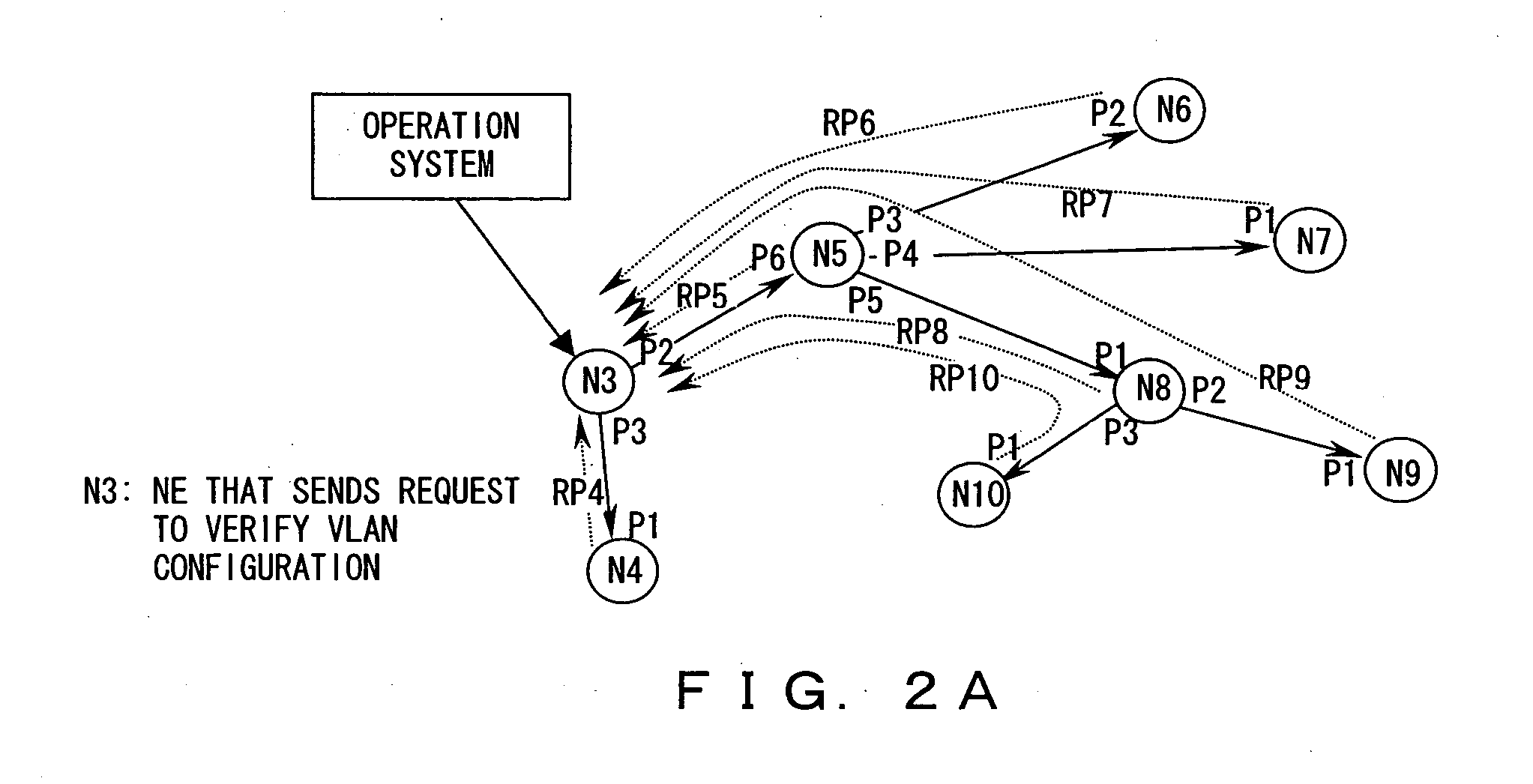
[0034]FIGS. 2A through 2C are provided to explain a method for keeping track of topology (the states of nodes interconnections) of a given virtual LAN, according to a first embodiment of the present invention.

[0035]FIG. 2A is a diagram showing a configuration example of a virtual LAN where keeping track of the states of nodes interconnections can be implemented by the first embodiment of the present invention (FIGS. 2B and 2C will be described later).

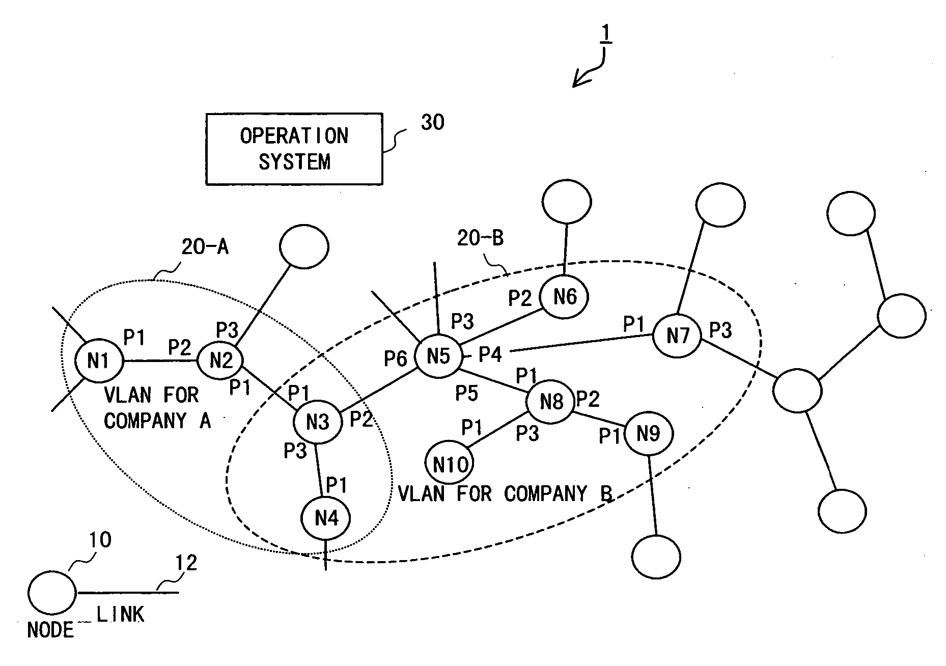
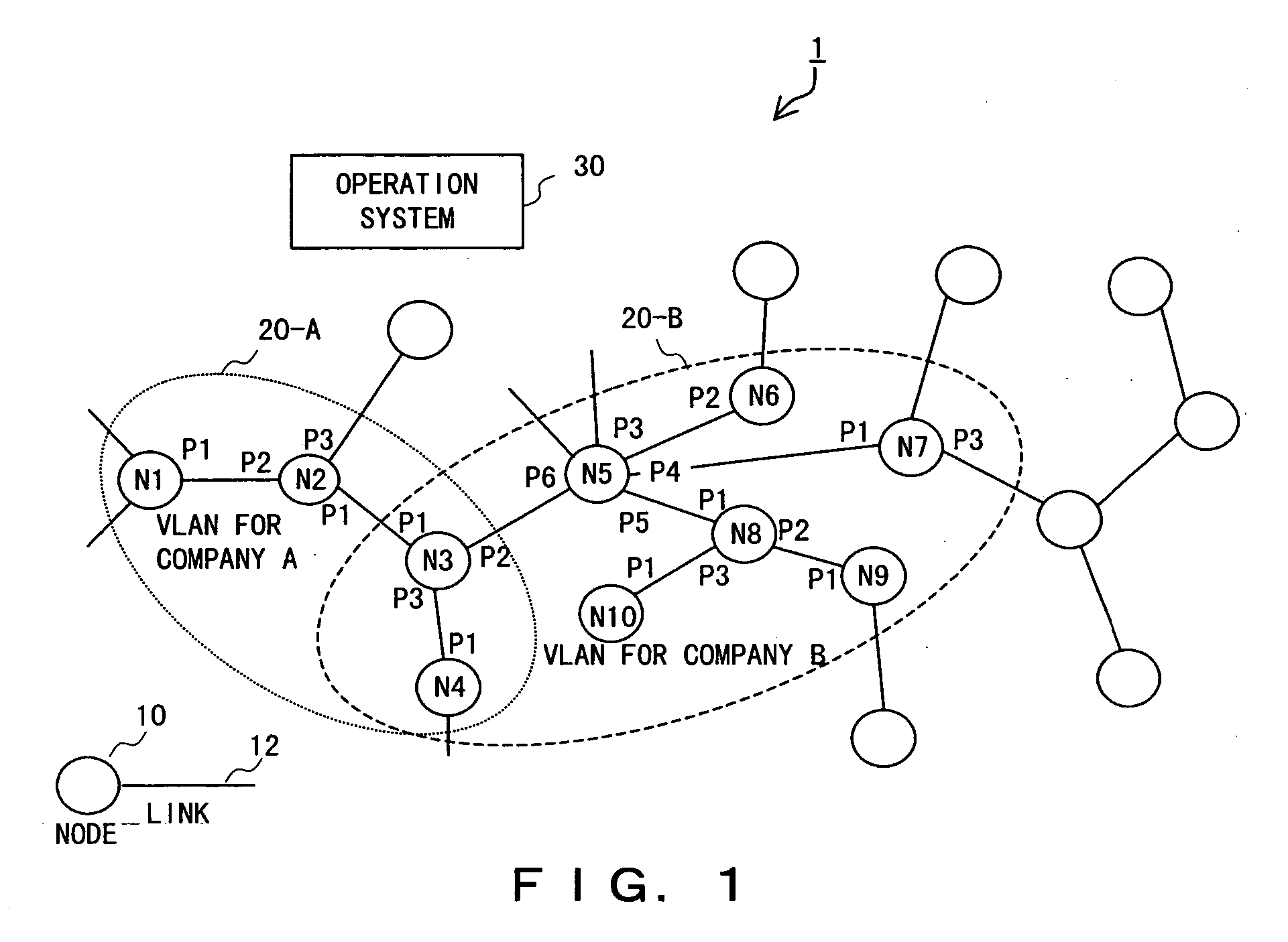
[0036] The network system of FIG. 2A is the same as the virtual LAN for company B in FIG. 1, except that the nodes, virtual LAN, and operation system are identified by references 10a, 20a, 30a instead of 10, 20, 30.

[0037]FIG. 3 is a block diagram showing an example of structure of the operation system 30a in FIG. 2A.

[0038] In FIG. 3, the operation system 30a that is a network management system of the present invention comprises a computer-base control section 31, a large-capacity storage device 32 which stores virtual LAN descriptio...

second embodiment

[0104] A second embodiment of the present invention is described with reference to FIGS. 14 through 16. FIG. 14 is a diagram illustrating a method in which the verification requesting NE sends first request packets to verify topology hop by hop across a virtual LAN to be verified and obtains the addresses of nodes constituting the virtual LAN to be verified and the number of hops from the verification requesting NE from first reply packets, according to the second embodiment of the present invention.

[0105] Referring to FIG. 14, a first request packet to verify topology that the verification requesting NE sends comprises the destination address, source address, VLAN tag which is the ID of the virtual LA to be verified, a value of TTL (Time To Live), TTL base, and OAM type which designates the packet type. The value of TTL is determined, taking the maximum number of allowable hops into consideration. In the example of FIG. 14, the verification requesting NE sends the first request pa...


PUM


Abstract

An arbitrary node that belongs to a virtual LAN sends a request packet including a count value indicating the number of communication hops across nodes to each of its adjacent nodes that belong to the virtual LAN and are adjacent. Upon receiving the request packet, each of the adjacent nodes sends the request packet in which the count value is incremented or decremented, as predetermined, to each of its adjacent nodes that belong to the virtual LAN and are adjacent to the node, excluding a sender of the request packet received, and sends a reply packet including the sender's address (sender address), an address of the node that is a replying node (replying node address), and the count value to a given return destination. The return destination collects reply packets sent thereto and keeps track of the topology of the nodes constituting the virtual LAN from information contained in the reply packets.

Description

BACKGROUND OF THE INVENTION [0001] 1. Field of the Invention [0002] The present invention relates to an Ethernet network or the like and, more particularly, to a technique for keeping track of virtual LAN topology set up on the Ethernet network. [0003] 2. Description of the Related Art [0004] When telecommunications carriers and the like (type one telecommunications carriers which are generally termed carriers) that possess their own infrastructures required to provide services provide communications services, it is general practice to organize and operate multiple so-called virtual local area networks (LANs) in which nodes constituting their own Ethernet networks are logically grouped and allocated to companies which are their customers, using a virtual LAN technology (for example, IEEE 802.1Q). This kind of service is generally called a wide area LAN service or wide area L2 (layer 2) service. [0005]FIG. 1 is a diagram showing an example of communications network infrastructure tha...

Claims


Application Information

Patent Timeline
Patent Type & Authority Applications(United States)
IPC IPC(8): H04L12/46
CPCH04L12/4641H04L45/26H04L45/02
Inventor KAWARAI, KENICHIKANEKO, HIROYUKITAJIMA, KAZUYUKITAKATORI, KOU
Owner FUJITSU LTD
Why Eureka
Try Eureka