
System and method for DSL subscriber identification over ethernet network

a subscriber identification and ethernet network technology, applied in the field of data communication systems, can solve the problems of failure to meet the other two requirements listed above, limited dslam id and port id space, and proved difficul

Active Publication Date: 2006-11-02
CISCO TECH INC
View PDF89 Cites 138 Cited by
  • Summary
  • Abstract
  • Description
  • Claims
  • Application Information

AI Technical Summary

Benefits of technology

The patent text discusses the use of Ethernet technology in data communication networks and the difficulty of achieving direct subscriber traffic to feature servers without any ambiguity. The text describes proposals for incorporating DHCP relay agents or PPPOE intermediate agents into the network edge device to solve the problem of identifying the subscriber at the feature server, but they fail to satisfy the other two requirements mentioned earlier. The technical effect of the patent text is to provide a solution for directing subscriber traffic to a given feature server, identifying the subscriber at the feature server, and directing feature server traffic to a given subscriber in the reverse direction without any ambiguity.

Problems solved by technology

However, achieving the three basic requirements of: (1) directing subscriber traffic to a given feature server depending on the requested service; (2) identifying the subscriber at the feature server; and (3) directing feature server traffic to a given subscriber in the reverse direction—all without any ambiguity—has proven difficult.
Although this proposal solves the problem of identifying the subscriber at the feature server, it fails to satisfy the other two requirements listed above.
This proposal, however, suffers from several drawbacks that include limited DSLAM ID and port ID space, problems with reverse mapping of the provider MAC address to a subscriber MAC address, and security issues.
Additionally, this approach is inadequate for multipoint applications where a separate broadcast domain (e.g., separate VLAN) is needed per service instance.

Method used


Image

  • System and method for DSL subscriber identification over ethernet network
  • System and method for DSL subscriber identification over ethernet network
  • System and method for DSL subscriber identification over ethernet network

Examples


Embodiment Construction

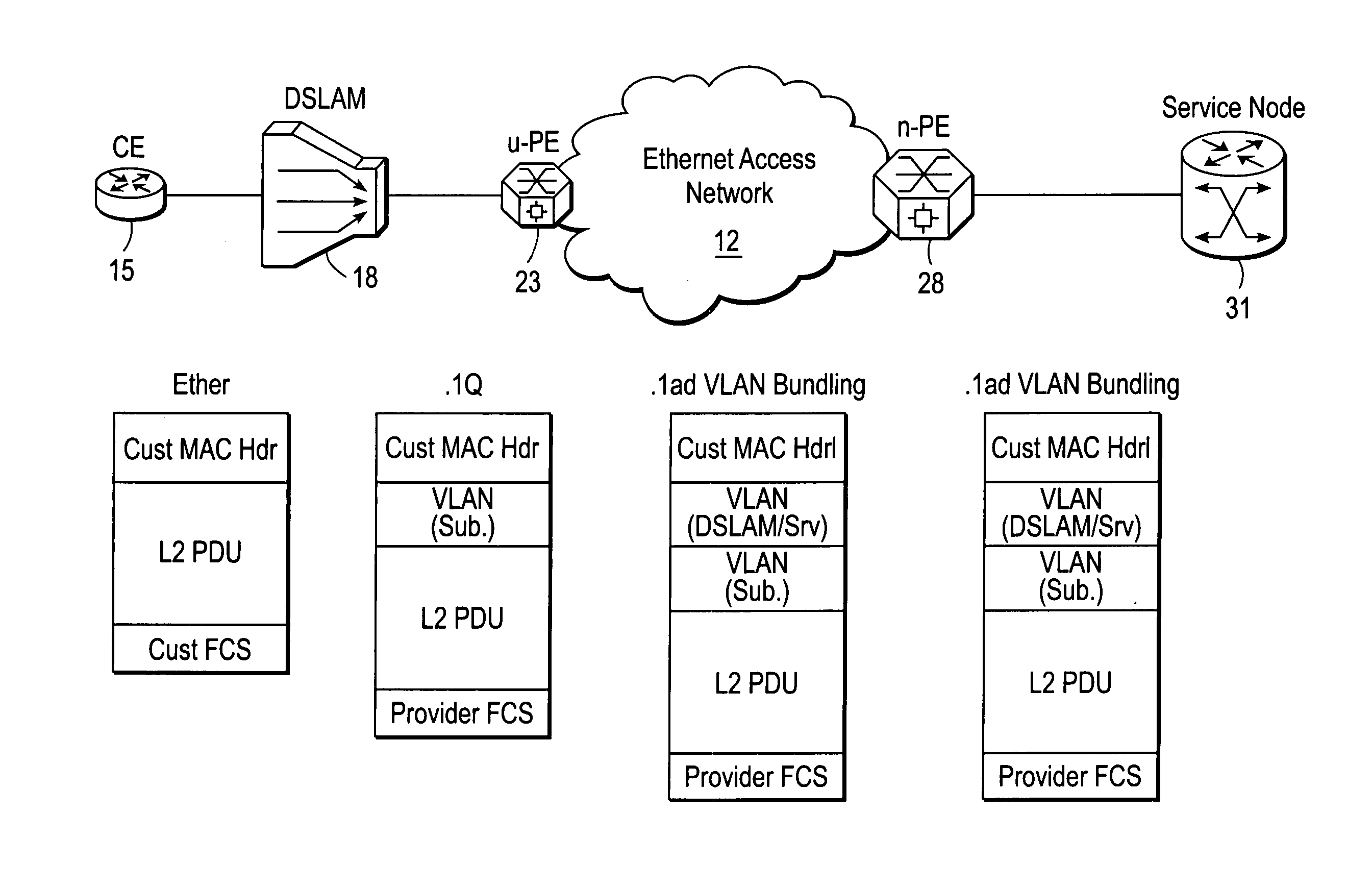
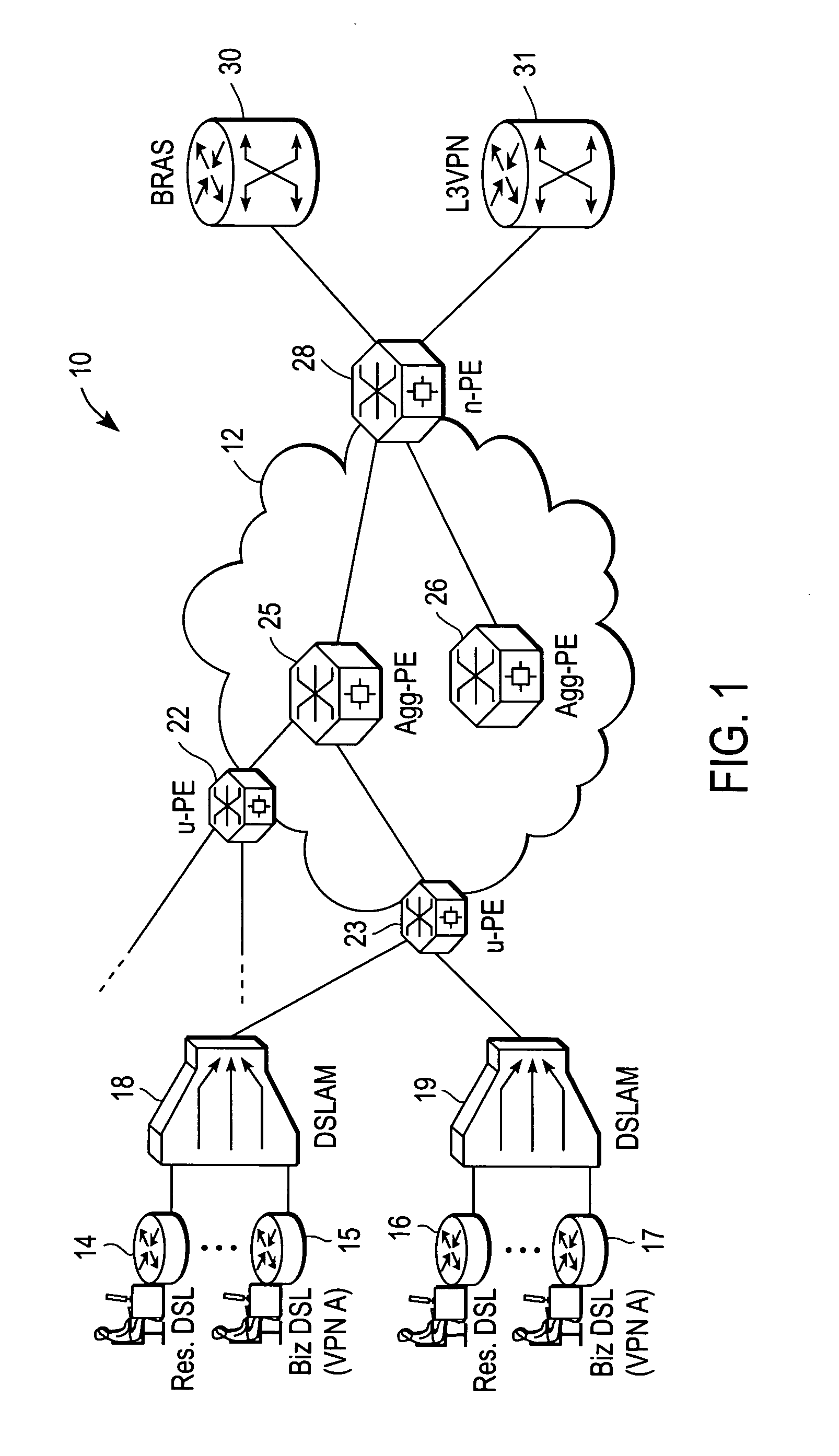
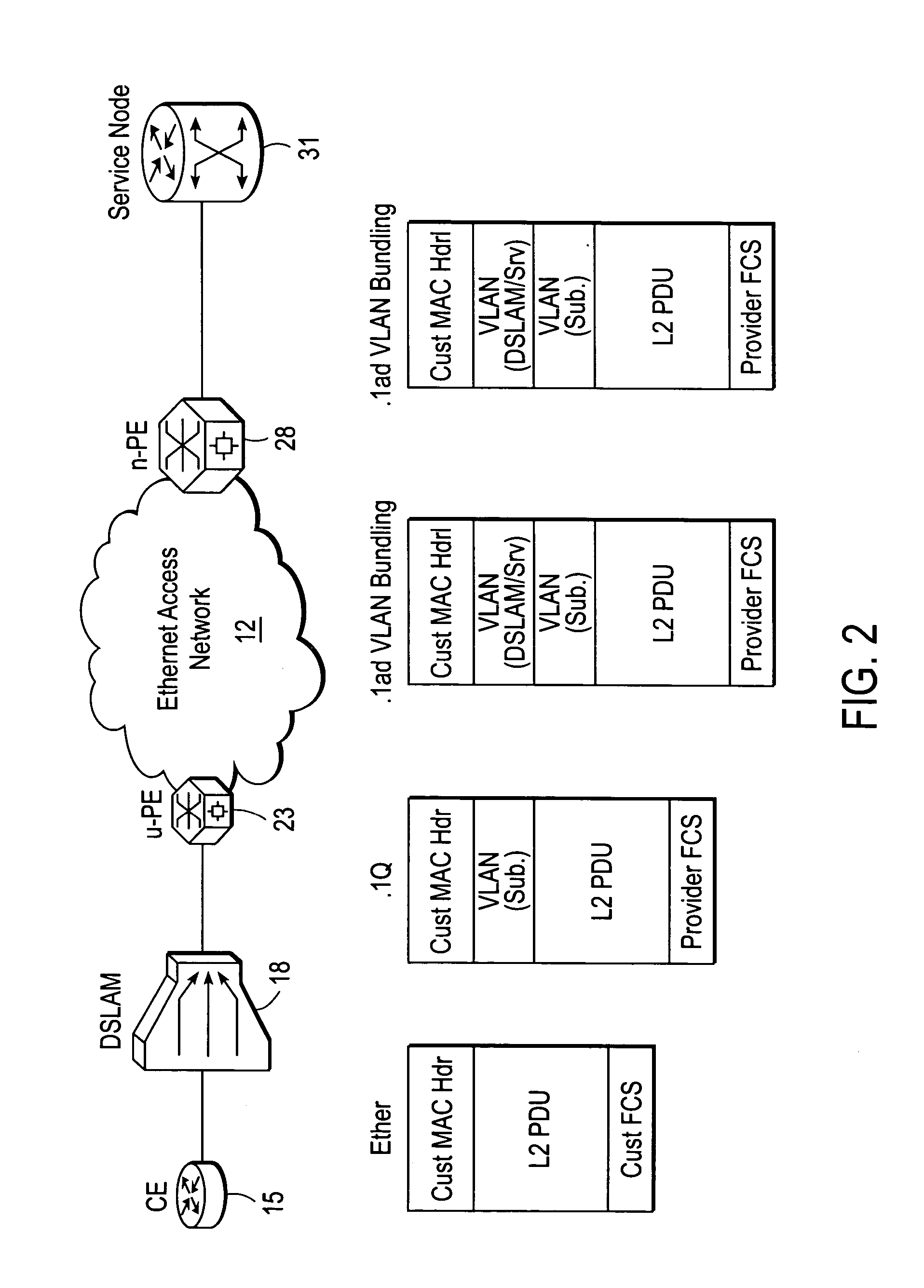
[0016] A DSL network VLAN bundling mechanism that provides DSL subscriber identification over an Ethernet network, and which further provides feature server selection and forwarding of subscriber traffic to a given feature server, and in the reverse direction forwarding traffic back to a given subscriber without ambiguity, is described. In the following description specific details are set forth, such as device types, protocols, configurations, etc., in order to provide a thorough understanding of the present invention. However, persons having ordinary skill in the networking arts will appreciate that these specific details may not be needed to practice the present invention.

[0017] A computer network is a geographically distributed collection of interconnected subnetworks for transporting data between nodes, such as intermediate nodes and end nodes. A local area network (LAN) is an example of such a subnetwork; a plurality of LANs may be further interconnected by an intermediate ne...


PUM


Abstract

A DSLAM aggregation topology VLAN bundling mechanism includes an edge device port that receives a packet from a Digital Subscriber Line Access Multiplexer (DSLAM) device, the packet including an inner Virtual Local Area Network (VLAN) tag that identifies a Digital Subscriber Line (DSL) subscriber. A processor of the edge device adds an outer VLAN tag to the packet, the outer VLAN tag identifying the DSLAM and a destination server coupled to an Ethernet access network. It is emphasized that this abstract is provided to comply with the rules requiring an abstract that will allow a searcher or other reader to quickly ascertain the subject matter of the technical disclosure. It is submitted with the understanding that it will not be used to interpret or limit the scope or meaning of the claims. 37 CFR 1.72(b).

Description

RELATED APPLICATIONS [0001] The present application is related to co-pending application Ser. No. ______ filed ______, entitled, “Metro Ethernet Network With Scaled Broadcast And Service Instance Domains”; filed , entitled, “A Comprehensive Model For VPLS”; and Ser. No. ______ filed ______, entitled, “Scalable System And Method For DSL Subscriber Traffic Over An Ethernet Network”, which applications are assigned to the assignee of the present application.FIELD OF THE INVENTION [0002] The present invention relates generally to data communications systems; more specifically, to subscriber access and communications over a high-speed network. BACKGROUND OF THE INVENTION [0003] Digital Subscriber Line (DSL) technology is widely-used today for increasing the bandwidth of digital data transmissions over the existing telephone network infrastructure. In a typical system configuration, a plurality of DSL subscribers are connected to a service provider (SP) network through a Digital Subscribe...

Claims


Application Information

Patent Timeline
Patent Type & Authority Applications(United States)
IPC IPC(8): H04L12/56
CPCH04L12/2881H04L45/00H04L12/66H04L12/465
Inventor SAJASSI, ALI
Owner CISCO TECH INC
Learn More