
System and method for providing lifeline power service to digital subscriber line customers

a technology for providing lifeline power and digital subscriber lines, applied in data switching networks, current supply arrangements, high-level techniques, etc., can solve the problems of high cost of central power delivery, high cost of operating companies, and increased power requirements, and achieve the effect of saving wattag

Inactive Publication Date: 2006-06-06
LUCENT TECH INC
View PDF4 Cites 63 Cited by
  • Summary
  • Abstract
  • Description
  • Claims
  • Application Information

AI Technical Summary

Problems solved by technology

These technologies are expensive to the operating companies because they require the operating company to physically rewire an entire community from each customer premise to a local switching office.
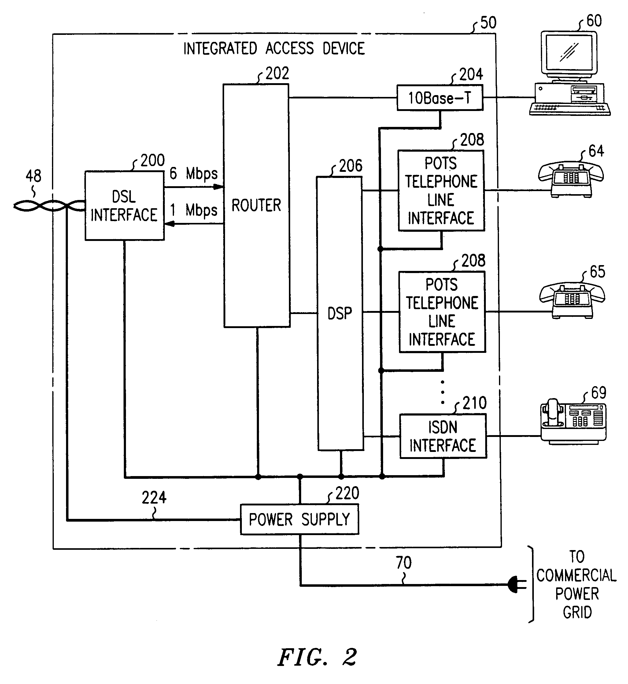
One issue that each DSL service provider must face is how the customer premise integrated access device is to be powered.
However, the integrated access device requires power at all times, and requires more power than a POTS telephone.
Thus, central power delivery is a very expensive proposition for the operating company.
One issue with VoDSL when power is provided by the power company is that, if the power goes out at the consumer premise, the customer can no longer use either the data terminal or, more importantly, the telephones.
This is a problem in the art in that many regulatory agencies require emergency (911) service (“lifeline service”) even during periods of power outages.
This solution, however, causes as many problems as it solves.
In normal operation, an integrated access device does not use the batteries and the user does not know (or care) whether the batteries are fully charged or not.
Such a situation is not acceptable to most regulatory agencies.
However, this monitoring usually includes sending crafts people to the customer premise to replace batteries, etc. which is the most expensive method of monitoring anything.
Therefore, a problem in the art is that there is no reliable backup system or method for providing power for lifeline service to commercially powered voice over DSL customers.

Method used


Image

  • System and method for providing lifeline power service to digital subscriber line customers
  • System and method for providing lifeline power service to digital subscriber line customers
  • System and method for providing lifeline power service to digital subscriber line customers

Examples


Embodiment Construction

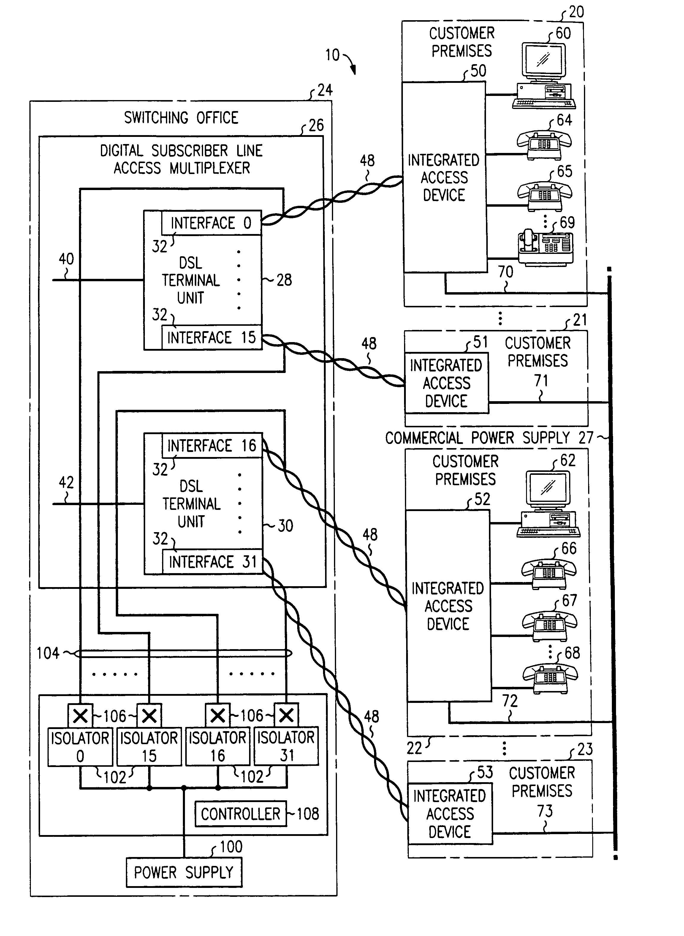
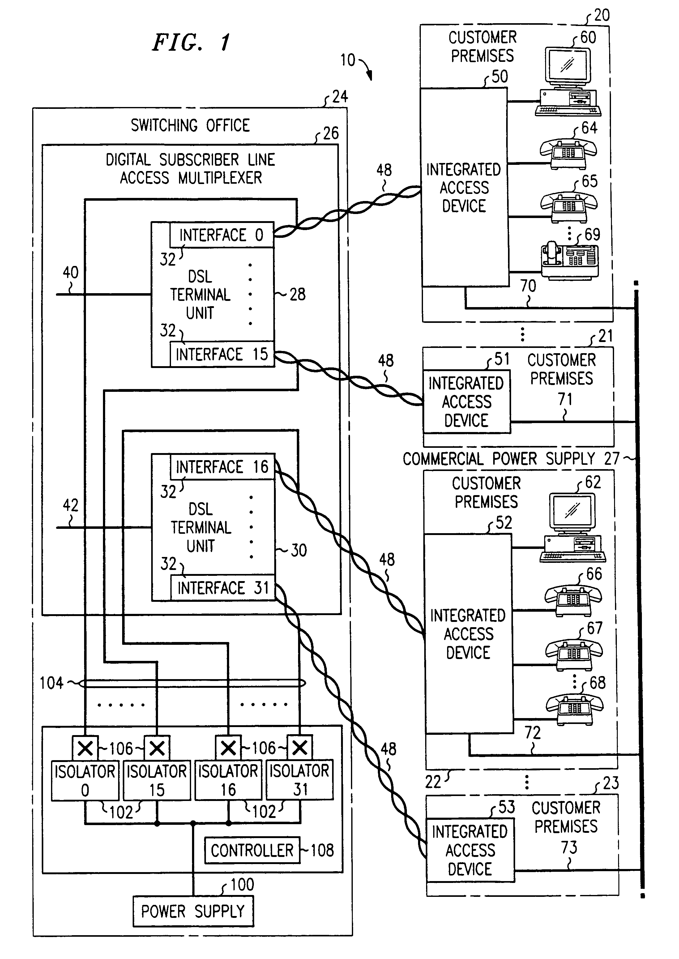
[0015]FIG. 1 illustrates a block diagram in which a lifeline service for voice over DSL according to this invention may be implemented. FIG. 1 is a block diagram of a local service region 10 comprising a plurality of customer premises 20, 21, 22 and 23, which are served by a switching office 24. Customer premises 20–23 are also served by various portions of the commercial power grid 26.

[0016]Switching office 24 includes a digital subscriber line access multiplexer (DSLAM) 26. DSLAM 26 includes, in this exemplary embodiment, DSL terminal units 28 and 30. Each DSL terminal unit 28 and 30 supports a plurality (16 in this exemplary embodiment) of interfaces 32 for terminating twisted-wire pair from customer premise 20–23. As is known in the art, DSL terminal units 28 and 30 receive data from customer premises 20–23, multiplex the data into one stream and send it out on lines 40 and 42, respectively, for further processing. In the opposite direction, DSL terminal units 28 and 30 receive ...


PUM


Abstract

A system and method that provides lifeline service to DSL customers when a loss-of-power message is sent to the central office from an integrated access device on the customer premise. If a predetermined number of loss-of-power messages are received then power is provided to the integrated access device from the central office. To this end, a power supply at the central office provides power through an isolator circuit to a relay. The relay is connected through to the twisted pair to the integrated access device. The data connection may also be powered in this manner or, in order to save further wattage, the data connection may be disconnected for the duration of the power outage.

Description

[0001]This is a continuation of application Ser. No. 09 / 650,050 filed on Aug. 29, 2000, now abandoned.FIELD OF THE INVENTION[0002]This invention relates to the field of digital subscriber lines and, more particularly, to providing power to digital subscriber line customer premise equipment in order to maintain service during times of power outages.BACKGROUND OF THE INVENTION[0003]Most telephone operating companies have an infrastructure of twisted-pair copper wire (also referred to as tip-ring pairs) connecting a telephone at a customer premise to a switching office. While this has been adequate for voice service for over a hundred years, modern data technologies are taxing the bandwidth limitations of twisted-pair service. Some operating companies are experimenting with fiber optic to the home, cable television (CATV) equipment, etc., in order to increase bandwidth for home and business use. These technologies are expensive to the operating companies because they require the operat...

Claims


Application Information

Patent Timeline
Patent Type & Authority Patents(United States)
IPC IPC(8): H04M1/00H04M19/00
CPCH04M19/001Y02D30/70
Inventor POSTHUMA, CARL ROBERT
Owner LUCENT TECH INC
Learn More