Ultrasonic diagnostic apparatus

Inactive Publication Date: 2005-12-01
OGASAWARA YOICHI
View PDF28 Cites 7 Cited by
  • Summary
  • Abstract
  • Description
  • Claims
  • Application Information

AI Technical Summary

Benefits of technology

[0024] According to such structures, realized is an ultrasonic diagnostic apparatus with which MTTs can be derived with assured accuracy and with high reproducibility through short-time scanning.

Problems solved by technology

The issue here is that, the contrast agent used for ultrasonic diagnosis is composed of very-small bubbles, and has such a peculiar physical property that the contrast agent itself may be collapsed and vanished.
Thus, simply applying the technique so far used with the MTT in other diagnostic apparatuses cannot realize the quantitative assessment with assured objectivity and accuracy.
However, the following problems are not yet solved to put the MTT into practical use in the ultrasonic diagnostic apparatus, for example.
The first problem is the varying MTTs due to uneven beam shapes.
Moreover, using the contrast agent bubbles requires the longer measurement time compared with TIC measurement with other types of medical equipment.
This is because every time scanning is done, the very-small bubbles being the contrast agent collapse and vanish, and thus resetting is required.
If so, however, it is difficult to securely keep the scanning cross section at the same position.
There is a possibility of checking the cross section by performing so-called monitor mode scanning with low sound pressure level not to collapse nor vanish the very-small bubbles, however, this requires to retain the probe for a long absolute time.
Still more the long-time administration of the contrast agent for ultrasound, and the resulting long-time examination will be disadvantageous for doctors, operators, and patients.
Furthermore, there may be a case where the very-small bubbles are not fully collapsed or vanished if the contrast agent is of a type hardly collapsing or vanishing, if the contrast agent is high in concentration, or if the transmission sound pressure is low.
As such, if the bubbles are not fully collapsed or vanished, it results in the following drawbacks.
Thus, the flow volume of the very-small bubbles, i.e., blood flow rate, cannot be correctly obtained, thereby failing in deriving correct MTTs after all.
Thirdly, as described in the foregoing, due to attenuation of the transmission ultrasound or attenuation of the reflected ultrasound, nearly no signal will be returned if the depth reaches at a certain point.

Method used


Image

  • Ultrasonic diagnostic apparatus
  • Ultrasonic diagnostic apparatus
  • Ultrasonic diagnostic apparatus

Examples


first embodiment

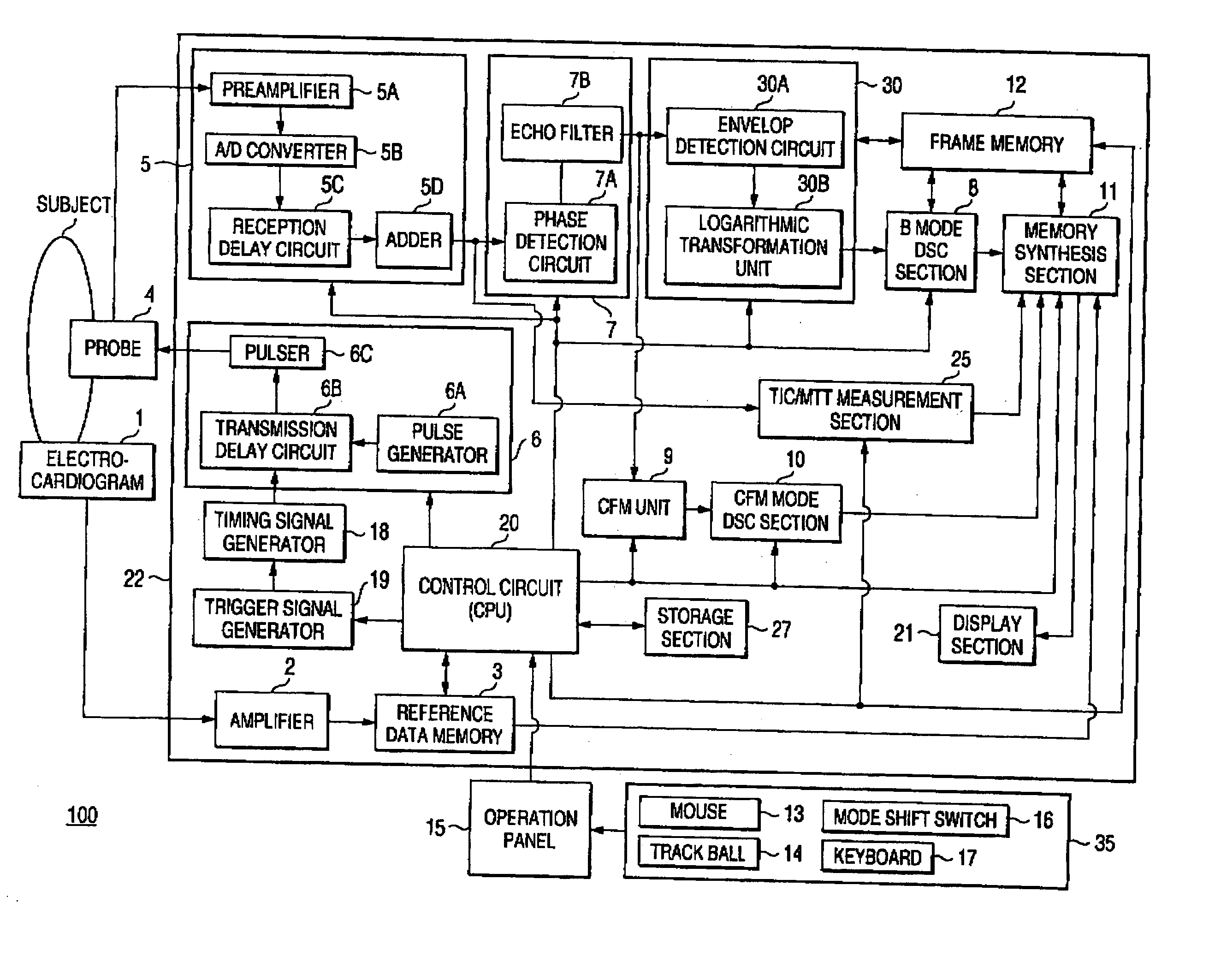
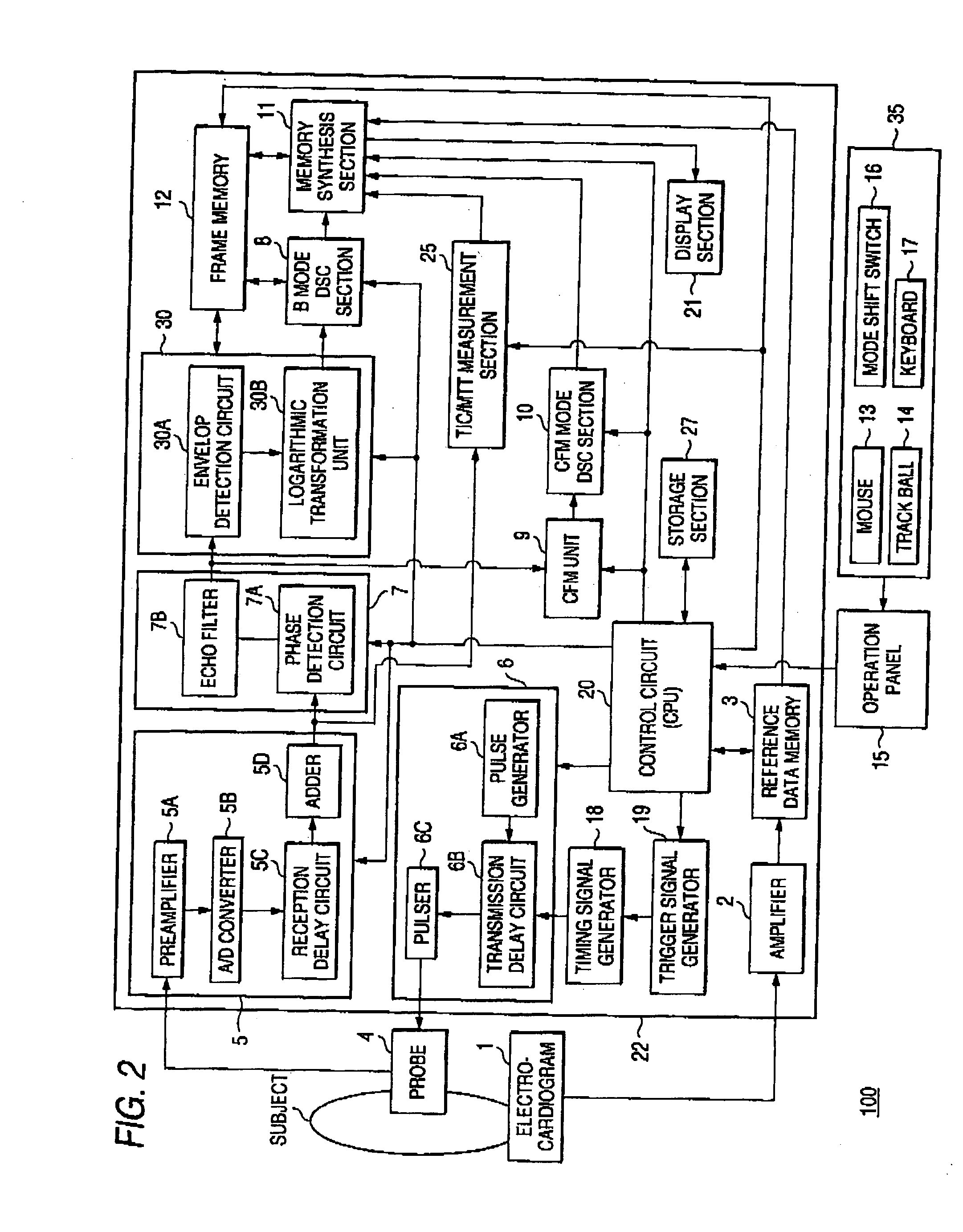
[0040] First of all, described is the structure of an ultrasonic diagnostic apparatus 100 of a first embodiment by referring to FIG. 2. The ultrasonic diagnostic apparatus 100 of the present embodiment is the one performing TIC / MTT measurement utilizing RF data (data after phase addition) as will be described later.

[0041]FIG. 2 is a block diagram showing the structure of the ultrasonic diagnostic apparatus 100. As shown in FIG. 2, the present ultrasonic diagnostic apparatus 100 is structured by an electrocardiogram (ECG) 1, an ultrasonic probe 4, an apparatus body 22, an operation panel 15, and an input unit 35. In the below, each of those components will be described.

[0042] The electrocardiogram (ECG: ElectroCardioGram) 1 measures a graph having recorded the time-varying electrical phenomena of a subject's heart, i.e., electrocardiogram. Electrocardiogram waveform signals detected by the electrocardiogram 1 are forwarded to reference data memory 3 via an amplifier 2, and if requi...

second embodiment

[0118] In a second embodiment, shown is an ultrasonic diagnostic apparatus 102 for executing a TIC / MTT measurement process based on IQ data (data having been subjected to phase detection by the receiver section 7 but not yet subjected to the process by the B-mode unit 30 or the CFM unit).

[0119]FIG. 11 is a block diagram showing the structure of the ultrasonic diagnostic apparatus 102 of the present embodiment. In FIG. 11, the TIC / MTT measurement section 25 receives the IQ data having been subjected to phase detection from the receiver section 7 to go through the TIC / MTT measurement process. This TIC / MTT measurement process is similar to the first embodiment. As to the effective information extraction process utilizing the IQ data, it is possible to execute that in a similar manner to the first embodiment.

[0120] With such a structure, the effects similar to the first embodiment can be achieved. In the second embodiment, due to high-speed calculation and hardware limitation, the IQ ...

third embodiment

[0121] A third embodiment shows an exemplary TIC / MTT measurement process to be executed based on B-mode detection data (data having been subjected to envelop detection by the envelop detection circuit 30A but not yet subjected to logarithmic transformation by the logarithmic transformation unit 30B).

[0122]FIG. 12 is a block diagram showing the structure of an ultrasonic diagnostic apparatus 104 of the present embodiment. In FIG. 12, the TIC / MTT measurement section 25 receives, from the B-mode unit 30, the B-mode detection data having been subjected to envelop detection by the envelop detection circuit 30A to go through the TIC / MTT measurement process. This TIC / MTT measurement process is similar to the first embodiment. As to the effective information extraction process utilizing the B-mode detection data, it is possible to execute in a similar manner to the first embodiment.

[0123] With such a structure, the effects similar to the first embodiment can be achieved.

[0124] Actually, ...


PUM


Abstract

With respect to a scanning plane of a subject having been injected with a contrast agent, an ultrasound transmission section 6 transmits for a plurality of times an ultrasonic pulse of such an intensity capable of collapsing the contrast agent. An ultrasound reception section 5 receives an echo signal cluster from the subject based on the ultrasonic pulses, and generates a plurality of RF data items through addition of the echo signal cluster using an adder 5C. Based on the plurality of RF data items, a TIC / MTT measurement section 25 measures a time intensity curve (TIC), and then measures a mean transit time (MTT) of the blood flow based on the time intensity curve for display on a display section 21.

Description

CROSS-REFERENCE TO RELATED APPLICATIONS [0001] This is a Continuation Application of PCT Application No. PCT / JP02 / 08475, filed Aug. 22, 2002, which was not published under PCT Article 21(2) in English. [0002] This application is based upon and claims the benefit of priority from prior Japanese Patent Application No. 2001-251766, filed Aug. 22, 2001, the entire contents of which are incorporated herein by reference.BACKGROUND OF THE INVENTION [0003] 1. Field of the Invention [0004] The present invention relates to an ultrasonic diagnostic apparatus capable of quantitatively assessing blood flow behaviors using a contrast agent for ultrasound. [0005] 2. Description of the Related Art [0006] An ultrasonic diagnostic apparatus is medical image equipment with which tomographic images of soft tissues beneath the body surface are derived from a living body in a noninvasive manner by the ultrasonic pulse echo method, and has been popular in the Departments relating to hearts, abdominal regi...

Claims


Application Information

Patent Timeline
IPC IPC(8): A61B5/08A61B8/00A61B8/06A61B8/08A61B8/14G01S15/89
CPCA61B5/08A61B8/06A61B8/0858A61B8/13A61B5/7232A61B8/54G01S7/52085G01S15/102G01S15/8979A61B8/481
Inventor OGASAWARA, YOICHI
Owner OGASAWARA YOICHI
Why Eureka
Try Eureka