Method and device for generating sampling signal

Inactive Publication Date: 2006-10-17
INNOLUX CORP
View PDF5 Cites 0 Cited by
  • Summary
  • Abstract
  • Description
  • Claims
  • Application Information

AI Technical Summary

Benefits of technology

[0005]It is an object of the present invention to provide a method and a device for generating non-overlapping sampling signals so as to assure of data accuracy.

Problems solved by technology

Since the horizontal scanning circuit may have some inherent adverse factors rendered by the manufacturing process, the generated sampling pulses are likely to partially overlap.

Method used


Image

  • Method and device for generating sampling signal
  • Method and device for generating sampling signal
  • Method and device for generating sampling signal

Examples


Embodiment Construction

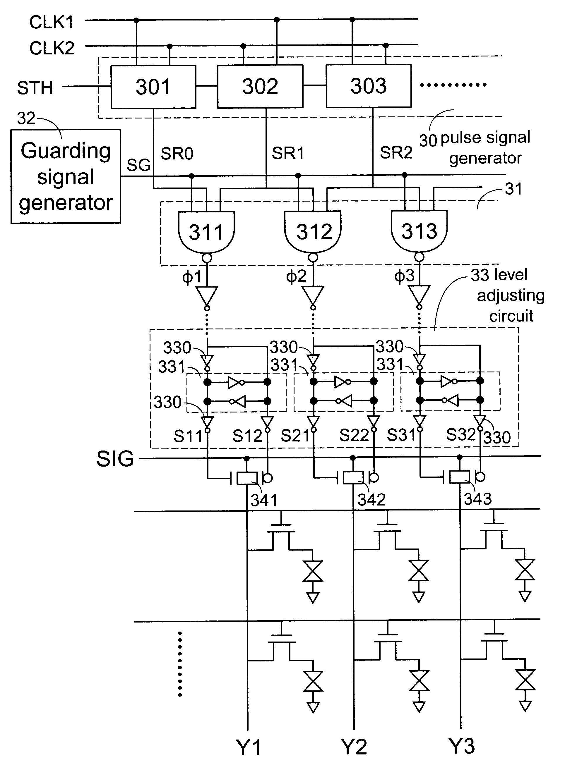
[0026]Please refer to FIG. 3, which illustrates a device for generating sampling signals for use in an active matrix display according to a preferred embodiment of the present invention. The device for generating sampling signals comprises a pulse signal generator 30, a logic operation circuit 31, a guarding signal generator 32 and a level adjusting circuit 33.

[0027]The pulse signal generator 30 comprises a plurality of data shift registers 301, 302, 303, . . . etc. A plurality of pulse signals SR0, SR1, SR2, . . . , are sequentially generated from these data shift registers in response to an enabling pulse signal STH and a pair of complementary clock signals CLK1 and CLK2. The guarding signal generator 32 is used to generate a guarding signal SG. FIG. 4(a) is timing waveform diagram showing relations between the enabling pulse signal STH, the pair of complementary clock signals CLK1, CLK2 and the guarding signal SG. The guarding signal SG has alternate high level and low level, whe...


PUM


Abstract

A method for generating sampling signals for use in an active matrix display is provided. Firstly, a plurality of pulse signals are sequentially generated, wherein every two adjacent pulse signals have a phase difference therebetween. Then, a guarding signal having alternate first level and second level is generated. Then, sampling signals associated with the pulse signals are outputted in response to the guarding signal being at the first level, and any sampling signal is exempted from outputting when the guarding signal is at the second level. A device for generating sampling signals for use in an active matrix display is also provided.

Description

FIELD OF THE INVENTION[0001]The present invention relates to a method and a device for generating sampling signals, and more particularly to a method and a device for generating sampling signals for use in an active matrix display.BACKGROUND OF THE INVENTION[0002]Liquid crystal displays (LCDs) are widely used in portable televisions, laptop personal computers, notebooks, electronic watches, calculators, mobile phones and office automation devices, etc. due to their advantages of small size, light weight, low driving voltage, low power consumption and good portability. A typical liquid crystal display comprises a driving circuit and an active matrix. The active matrix is generally implemented by a thin film transistor array, and driven by the driving circuit.[0003]FIG. 1 is a schematic circuit diagram illustrating the configuration of a conventional driving circuit of a liquid crystal display. The driving circuit of FIG. 1 comprises a horizontal scanning circuit 10 for asserting a pl...

Claims


Application Information

Patent Timeline
IPC IPC(8): G09G3/36
CPCG09G3/3688
Inventor TSENG, JUNG-CHUHWANG, WEI
Owner INNOLUX CORP
Why Eureka
Try Eureka