
Method and apparatus for controlling automatic exposure in a camera

a technology of automatic exposure and camera, applied in the field of camera systems, can solve the problems of conventional automatic exposure not effectively compensating for front-light or back-light scenes, image may be too bright, image may be too dark, etc., and achieve the effect of increasing the exposure tim

Active Publication Date: 2005-12-08
SAMSUNG ELECTRONICS CO LTD
View PDF10 Cites 24 Cited by
  • Summary
  • Abstract
  • Description
  • Claims
  • Application Information

AI Technical Summary

Benefits of technology

[0024] In this manner, the first brightness level is assigned increased weight value for the higher difference between the first and second brightness levels. Thus, the exposure time is more increased for the back-lighted scene, and is more decreased for the front-lighted scene.

Problems solved by technology

When the exposure time is too long, an image may be overly bright.
In contrast, when the exposure time is too short, an image may be too dark.
Therefore, the conventional automatic exposure may not effectively compensate for such front-lighted or back-lighted scenes.
However, a correction coefficient for each of the divided areas is predefined, and the brightness difference between the respective areas is not used in the exposure control.

Method used


Image

  • Method and apparatus for controlling automatic exposure in a camera
  • Method and apparatus for controlling automatic exposure in a camera
  • Method and apparatus for controlling automatic exposure in a camera

Examples


Embodiment Construction

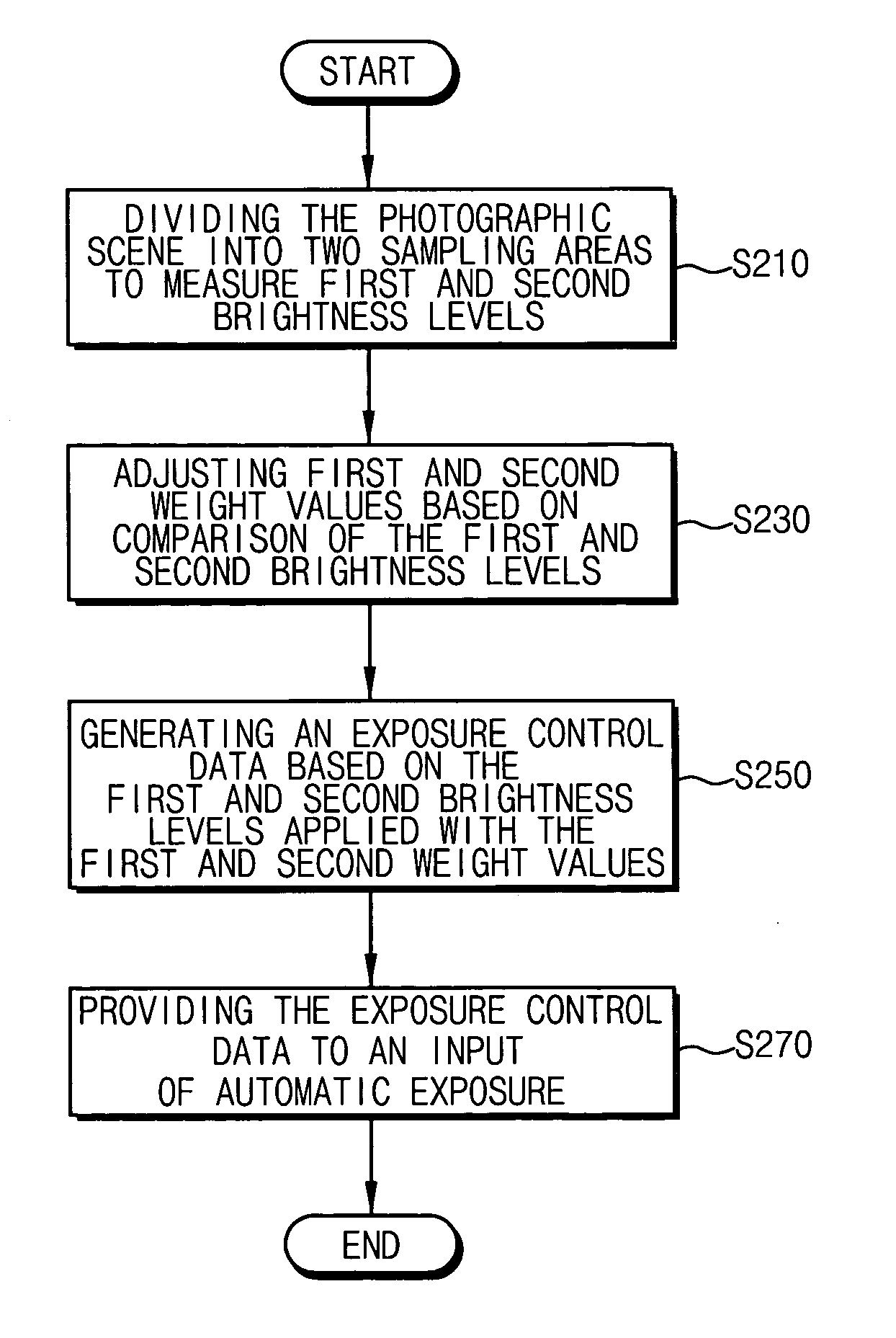
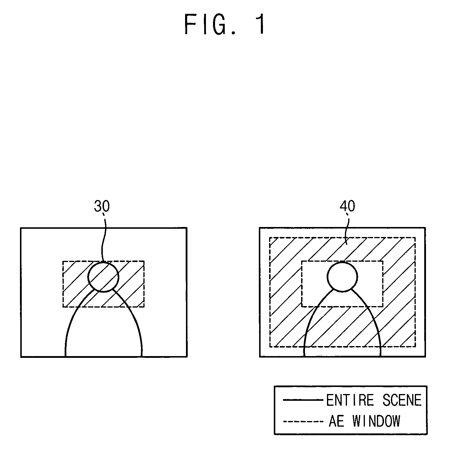
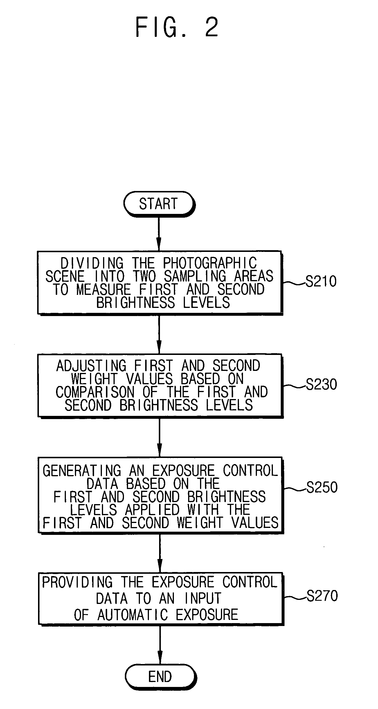
[0032]FIG. 1 shows a captured image divided into a first area 30 and a second area 40, according to an example embodiment of the present invention. FIG. 2 is a flowchart of steps for control of automatic exposure in a camera, according to an example embodiment of the present invention.

[0033] Referring to FIG. 1, the first area 30 of a captured image in a camera includes a main photographed subject, and the second area 40 includes a background scene, in one embodiment of the present invention. Generally, the main subject to be captured is mostly positioned in a central area that is the first area 30 of the captured image. In that case, the second area 40 corresponds to a peripheral area surrounding the main subject. In addition, the present invention may be practiced when the captured image is divided into two or more areas to measure respective brightness levels thereof.

[0034] Referring to FIG. 2, a first brightness level is extracted from the first area 30, and a second brightnes...


PUM


Abstract

For controlling exposure in a camera, first and second brightness levels of first and second areas of a captured image are determined. First and second weight values for the first and second brightness levels are determined with an increase of the first weight value for a higher difference between the first and second brightness levels. Exposure control data is generated from the first and second weight values and the first and second brightness levels.

Description

BACKGROUND OF THE INVENTION [0001] This application claims priority under 35 USC § 119 to Korean Patent Application No. 2004-52177, filed on Jul. 6, 2004, the contents of which are herein incorporated by reference in its entirety for all purposes. [0002] 1. Field of the Invention [0003] The present invention relates generally to camera systems, and more particularly to a method and apparatus for controlling automatic exposure in a camera. [0004] 2. Description of the Related Art [0005] Portable terminals, such as personal communication systems (PCS) and cellular phones, have become increasingly popular. Particularly, the portable terminal with a built-in camera, referred to as a camera phone, is widely used. In such a camera, an exposure time of each pixel needs to be controlled according to lighting conditions. When the exposure time is too long, an image may be overly bright. In contrast, when the exposure time is too short, an image may be too dark. [0006] Conventional automatic ...

Claims


Application Information

Patent Timeline
Patent Type & Authority Applications(United States)
IPC IPC(8): H04N5/235G03B7/08G03B7/093G03B7/28
CPCH04N5/2351H04N23/71H04N5/57
Inventor LEE, HYUNG-GUEN
Owner SAMSUNG ELECTRONICS CO LTD
Learn More