

Air sampler with parallel impactors
a sampler and impactor technology, applied in the field of air samplers with parallel impactors, can solve the problems of heavy weight and complicatedness of samplers including pumps and batteries, and achieve the effect of improving sample quality and reducing the cost of passive sampling
- Summary
- Abstract
- Description
- Claims
- Application Information
AI Technical Summary
Problems solved by technology
Method used
Image

Examples
example 1
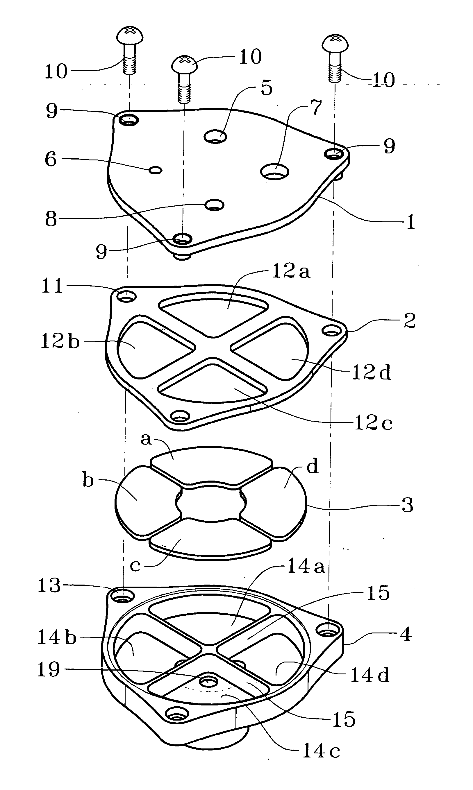
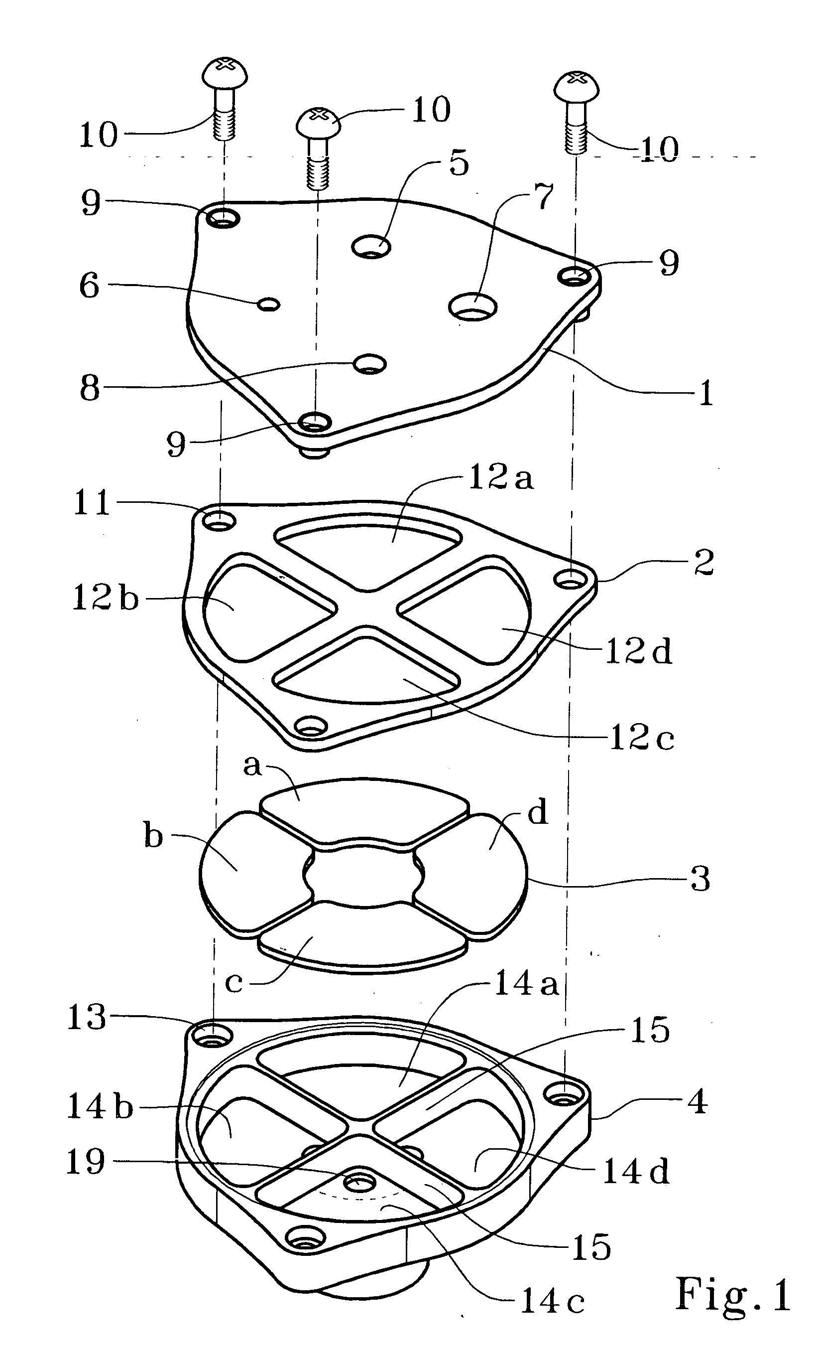
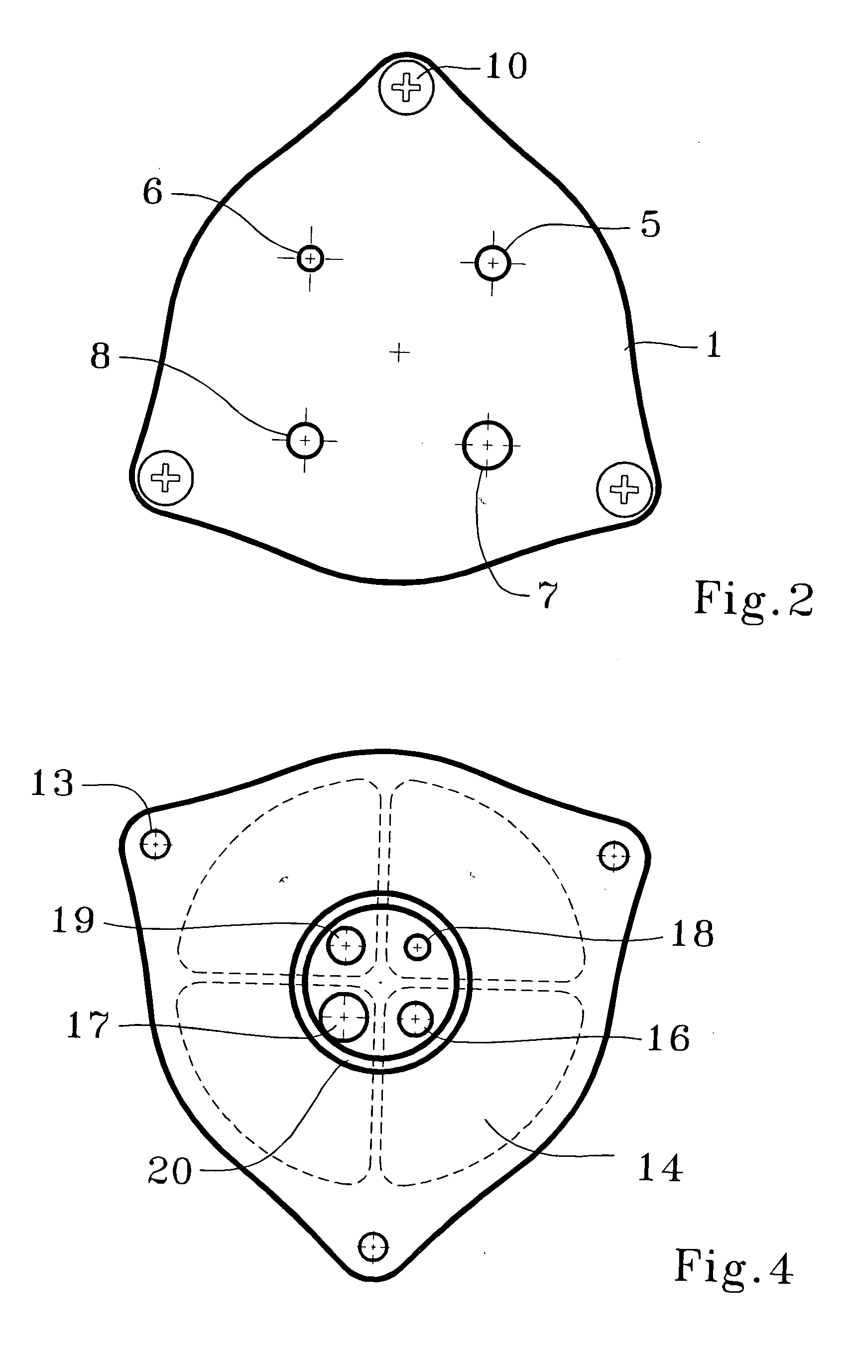
[0036] A sampler containing four parallel round-nozzle impactors and designed to approximate a respirable convention at 4.0 L / min (Table 1.) was machined and tested. The sampler incorporated a design similar to FIGS. 1-4 and the specifications of the 4-impactor design in Table 1 (Sampler 2). Experimental data are presented in FIGS. 5 and 6. Sampling efficiency was obtained by measuring particle concentration upstream and downstream of the sampler using an Aaerodynamic Particle Sizer (APS, Model 3320, TSI Inc., St. Paul, Minn.). FIG. 5 shows sampling efficiency of each separate impactor tested at 1.0 L / min (¼ of total flow). The dashed curve in FIG. 5 represents the respirable convention—the curve the sampler was designed to approximate. Table 1 shows that predicted d50 for impactors 1-4 at QS=1.0 L / min is 2.2, 3.5, 4.6 and 6.6 μm. Experimentally obtained 50% cut-off sizes were 2.7, 3.8, 4.7, and 6.0 μm accordingly (FIG. 6.). As can be seen the experimental data is in good agreement ...
PUM
| Property | Measurement | Unit |
|---|---|---|
| flow rate | aaaaa | aaaaa |
| sampling flow rate | aaaaa | aaaaa |
| flow rate | aaaaa | aaaaa |
Abstract
Description
Claims
Application Information