Latching separation system

a separation system and latching technology, applied in the field of mechanical connectors, can solve the problems of limiting the amount of testing that can be applied to the components affecting the reliability of the components, and preventing the testing of the joints that are actually flown, so as to reduce the force required

Inactive Publication Date: 2005-12-22
HOLEMANS WALTER
View PDF68 Cites 8 Cited by
  • Summary
  • Abstract
  • Description
  • Claims
  • Application Information

AI Technical Summary

Benefits of technology

[0003] Transport systems, such as rockets that transport satellites into space, vessels that transport submerged sections of ocean structures such as oil platforms, and the like, require a means for securely fastening different items together for transport, and reliably and easily unfastening the items for deployment. Multi-stage rockets also require a means for fastening the stages together, and reliably unfastening the stages as each stage is spent. In other situations, such as aircraft carrier based aircraft, the items are transported or stored in a disassembled state and require a means for rapidly fastening the items for deployment, and reliably and easily unfastening the items for subsequent storage or transport.
[0004] A variety of devices have been developed to secure two items together while also allowing the items to be separated quickly and reliably. In the aerospace industry, the common connection devices include bolts and bands that can be severed. Bolts are used to fasten the two items together, and an explosive charge is typically used to sever the bolts at the proper time, thereby unfastening the two items. Depending upon the application, ancillary devices such as springs may be used to urge the two items apart when the bolts are severed. To assure a reliable separation, the number of bolts used to fasten the two items is kept to a minimum; this results in load points at the bolts far in excess of the load imposed by a distributed fastening system.
[0005] Belt structures are commonly used to provide for a distributed load. A belt structure that is commonly employed to fasten items together is a “V-band”, typified by U.S. Pat. No. 4,715,565, “CLAMPING CONNECTION ASSEMBLY FOR SPACECRAFT”, issued a tension belt for securing a plurality of retainers against camming surfaces on 
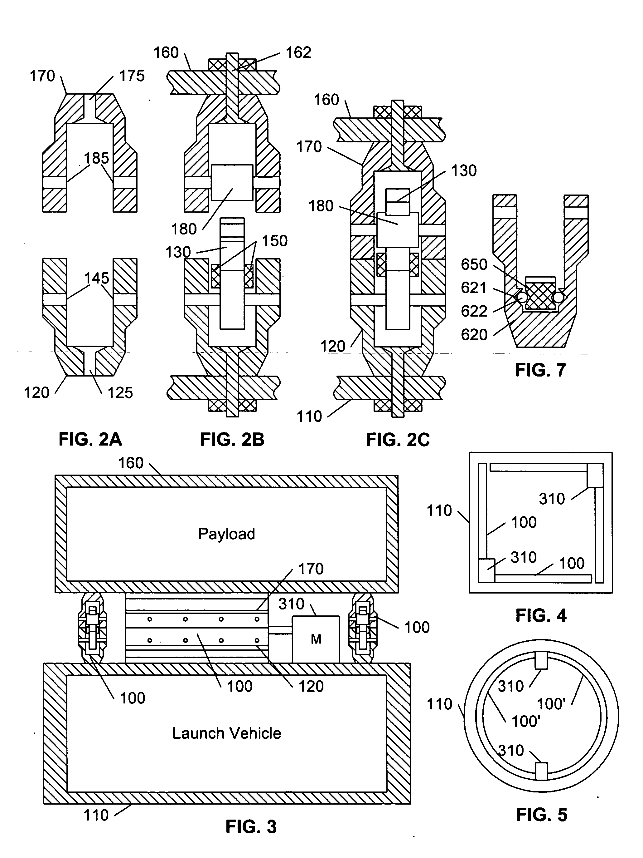
flange members on separable spacecraft component parts. A typical V-band embodiment consists of an upper ring attached to the payload, a lower ring attached to the launch vehicle, and a clampband that is circumferentially tensioned to the flanges of the upper and lower rings. The clampband is conventionally tensioned by bolts, and explosive bolt cutters are used to sever the bolts to release the tension. Because of the high tension requirements, the combined weight of the belt, clamps, and ancillary required devices is substantial (as much as 45 pounds for a 38 inch diameter V-band structure). The high tension requirements of V-bands often require specialized tools and instruments to tension the band. The high tension and high release shock effects also limits the reliable life of the components, thereby limiting the amount of testing that can be applied to the components that are actually flown.
[0010] It is an object of this invention to provide a non-explosive and reusable coupling system that provides for substantially bistable operation. It is a further object of this invention to provide a non-explosive and reusable coupling system that integrates both the coupling and decoupling means. It is a further object of this invention to provide a non-explosive and reusable coupling system that does not require exerting a radial force. It is a further object of this invention to provide a non-explosive and reusable coupling system that does not require a continuous perimeter of engaging elements.
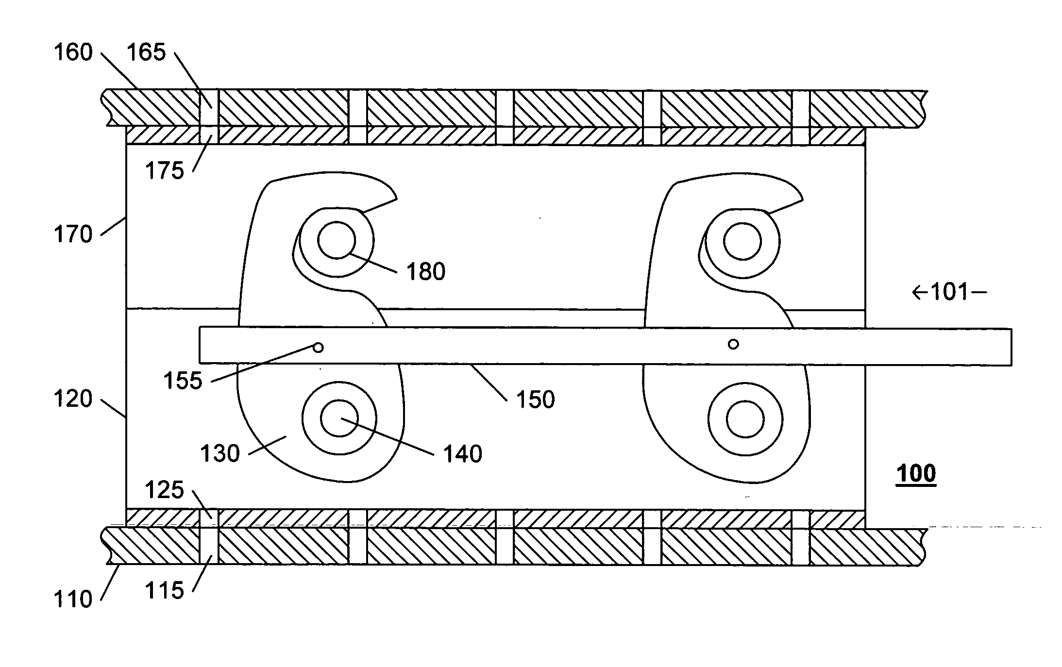
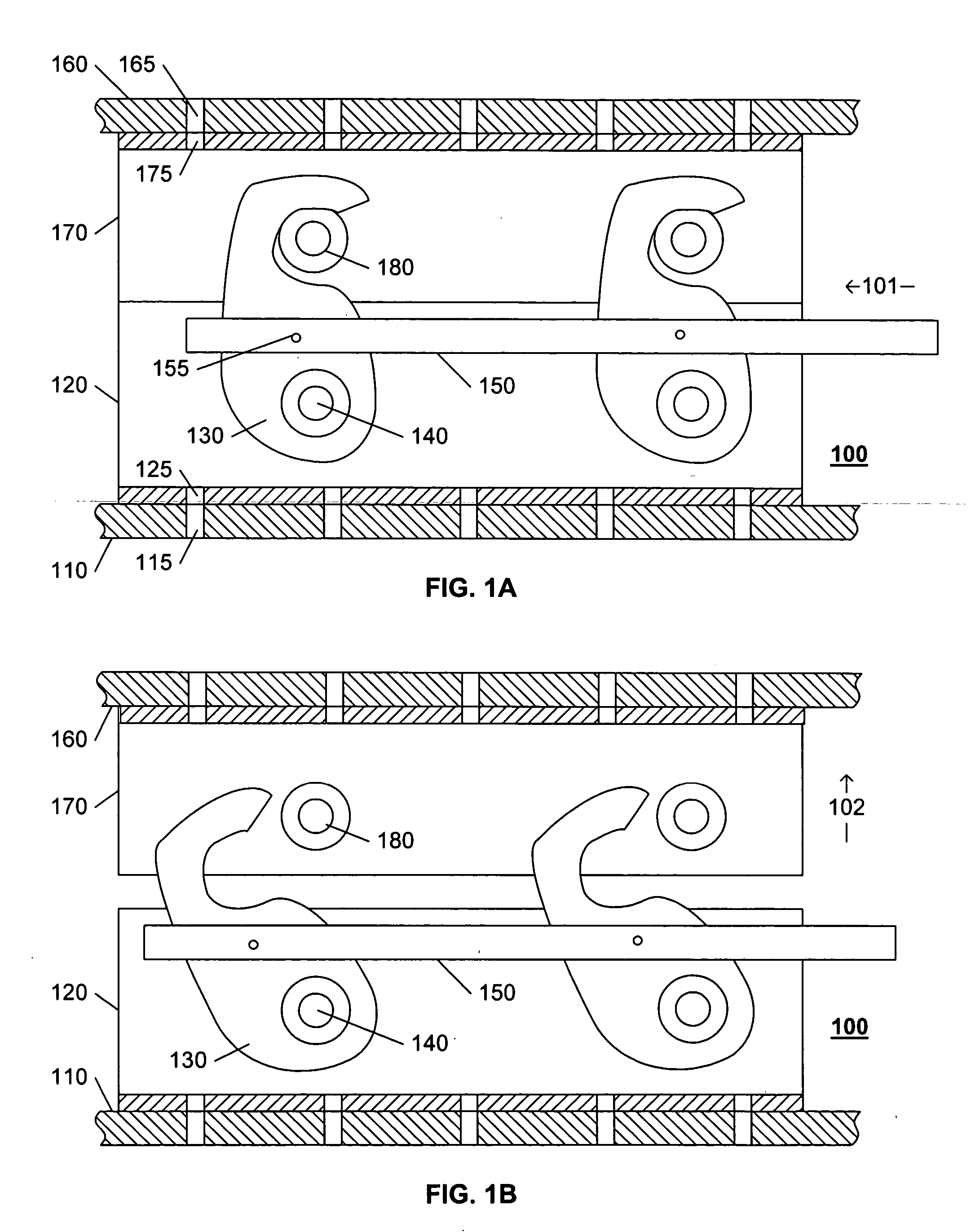
[0011] These objects, and others, are achieved by a coupling system that includes latching elements on a first structure that are configured to securely engage corresponding bearings on a second structure. When engaged, or when disengaged, the system is in a stable state, requiring no active force by the controlling system to maintain the system in each state. The coupling system includes a pair of coupling elements, one of which includes a plurality of latching elements, and the other of which includes a plurality of corresponding bearings. A lateral member provides simultaneous rotation of the plurality of latching elements to engage, or disengage, the latching elements from the bearings. Preferably, each latching element is coupled to the lateral member via a pinion that provides a mechanical advantage that substantially reduces the force required on the lateral member to effect the coupling or decoupling. Also preferably, the elements are formed from extruded aluminum forms, thereby providing for a relatively inexpensive and lightweight configuration.BRIEF DESCRIPTION OF THE DRAWINGS

Problems solved by technology

The high tension and high release shock effects also limits the reliable life of the components, thereby limiting the amount of testing that can be applied to the components that are actually flown.
The destructive nature of this separation system precludes testing of the joints that are actually flown.
Many launched vehicles have been lost due to a failure in the explosive separation system, and many satellites have been damaged due to explosive shock.
Each of the aforementioned separation connectors also imparts a substantial shock to the connected items upon separation, and the explosive nature of the devices used for separation introduce a risk of personal injury, particularly during pre-launch assembly and testing.
Because of the shock effects, such separation connectors are not commonly used on items that are routinely disassembled for storage or transport, and explosive joints are not commonly used on fragile devices, such as spacecraft / satellites.

Method used


Image

  • Latching separation system
  • Latching separation system
  • Latching separation system

Examples


Embodiment Construction

[0022] The invention is presented herein using the paradigm of a spacecraft separation system, because some of the features and benefits of this invention are particularly well suited for coupling, and decoupling, spacecraft. One of ordinary skill in the art will recognize, however, that the disclosed coupling system is not limited to spacecraft applications. Of particular note, this invention is well suited for coupling large structures or large components. In space applications, the coupling system of this invention can be used to facilitate the coupling of the components of space stations, or components of habitats that must provide sealed environments on other planets or moons. In terrestrial applications, the coupling system of this invention can facilitate the joining of pipes in difficult environments, such as the artic or open-water oil platforms; similarly, the building of habitats in these environments can be facilitated by coupling preformed structures. Other applications...


PUM


Abstract

Latching elements on a first structure are configured to securely engage corresponding bearings on a second structure, via a lateral member that drives all of the latching elements simultaneously. When engaged, or when disengaged, the system is in a stable state, requiring no active force by the controlling system to maintain the system in each state. Preferably, each latching element is coupled to the lateral member via a pinion that provides a mechanical advantage that substantially reduces the force required on the lateral member to effect the coupling or decoupling. Also preferably, the elements are formed from extruded aluminum forms, thereby providing for a relatively inexpensive and lightweight configuration that is particularly well suited for spacecraft applications.

Description

[0001] This application claims the benefit of U.S. Provisional Patent Application 60 / 555,663, filed 23 Mar. 2004, and U.S. Provisional Patent Application 60 / 619,805, filed 18 Oct. 2004.BACKGROUND AND SUMMARY OF THE INVENTION [0002] This invention relates to the field of mechanical connectors, and in particular to a connector that is suitable for coupling large objects, such as spacecraft to launch vehicles. [0003] Transport systems, such as rockets that transport satellites into space, vessels that transport submerged sections of ocean structures such as oil platforms, and the like, require a means for securely fastening different items together for transport, and reliably and easily unfastening the items for deployment. Multi-stage rockets also require a means for fastening the stages together, and reliably unfastening the stages as each stage is spent. In other situations, such as aircraft carrier based aircraft, the items are transported or stored in a disassembled state and requ...

Claims


Application Information

Patent Timeline
Patent Type & Authority Applications(United States)
IPC IPC(8): B63B21/08B64G1/64
CPCB64G1/641B63B21/08Y10T292/0914Y10T292/1021Y10T292/1079
Inventor HOLEMANS, WALTER
Owner HOLEMANS WALTER
Why Eureka
Try Eureka