Bifocal intraocular telescope for low vision correction
- Summary
- Abstract
- Description
- Claims
- Application Information
AI Technical Summary
Benefits of technology
Problems solved by technology
Method used
Image
Examples
Example
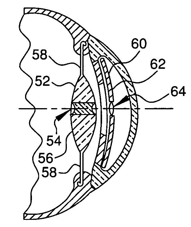
[0040]FIG. 8 shows a second embodiment of the present invention. In this embodiment, the natural lens of the eye is replaced with an artificial lens 52. The artificial lens 52 has a central portion 54, a peripheral portion 56, and is fastened into the posterior chamber by haptics 58. The peripheral portion 56 of the lens 52 is a generally converging lens, much like the natural lens which it replaces. The central portion 54, however, is a diverging lens with a high negative refractive index. An anterior implant 60 is located in the anterior chamber of the eye. The anterior implant 60 has a transparent peripheral portion 62 and a central portion 64. The central portion 64 is a lens with a high positive refractive index. The anterior implant central portion 64 is aligned with the artificial lens central portion 54, forming a telescope for enhancing low vision. The peripheral portion 62 has the same characteristics as peripheral portion 34 described above regarding the first embodiment ...
Example
[0041]FIG. 9 illustrates a third embodiment of present invention. In this embodiment, a first intraocular implant 66 is placed immediately adjacent the primary lens 68 and placed in the ciliary sulcus 69 of the posterior chamber by haptics 71. The illustrated primary lens 68 is a natural lens, but may also be an artificial intraocular lens. The central portion 70 of the implant 66 is a lens with a high negative refractive index and is surrounded by a peripheral portion 72, which has the same characteristics as portion 34 described above. A second intraocular implant 74 is placed in the anterior chamber of the eye. The second intraocular implant 74 has a central lens portion 76 with a positive refractive index and a peripheral portion 77 surrounding lens portion 76. The central portions 70, 76 of the two implants 66, 74 are aligned, forming a telescope as discussed above regarding the embodiment of FIGS. 1-4.
Embodiment of FIG. 10
Example
[0042]FIG. 10 shows a fourth embodiment of the present invention. In this embodiment, the intraocular implant 78 has a telescope portion 80 attached to a peripheral portion 82. The peripheral portion 82 is placed directly onto the primary lens 84 and is attached to the ciliary sulcus 83 by haptics 85. The illustrated primary lens is a natural lens, but may also be an artificial intraocular lens. The telescope portion 80, which is constructed in the same manner as previously discussed, extends through the iris. The peripheral portion 82 has the same characteristics as portion 34 described above.
Embodiment of FIGS. 11 and 12
PUM
Abstract
Description
Claims
Application Information
- R&D Engineer
- R&D Manager
- IP Professional
- Industry Leading Data Capabilities
- Powerful AI technology
- Patent DNA Extraction
Browse by: Latest US Patents, China's latest patents, Technical Efficacy Thesaurus, Application Domain, Technology Topic.
© 2024 PatSnap. All rights reserved.Legal|Privacy policy|Modern Slavery Act Transparency Statement|Sitemap