Power supply system and method thereof

a power supply system and entertainment lighting technology, applied in the field of entertainment lighting systems, can solve the problems of complex and elaborate systems, difficult, if not impossible, to use industry-standard communication protocols to operate entertainment lighting and effects systems

a power supply system and entertainment lighting technology, applied in the field of entertainment lighting systems, can solve the problems of complex and elaborate systems, difficult, if not impossible, to use industry-standard communication protocols to operate entertainment lighting and effects systems

US20050289279A1Inactive Publication Date: 2005-12-29CITY THEATRICAL

Image

  • Power supply system and method thereof
  • Power supply system and method thereof
  • Power supply system and method thereof

Examples


Embodiment Construction

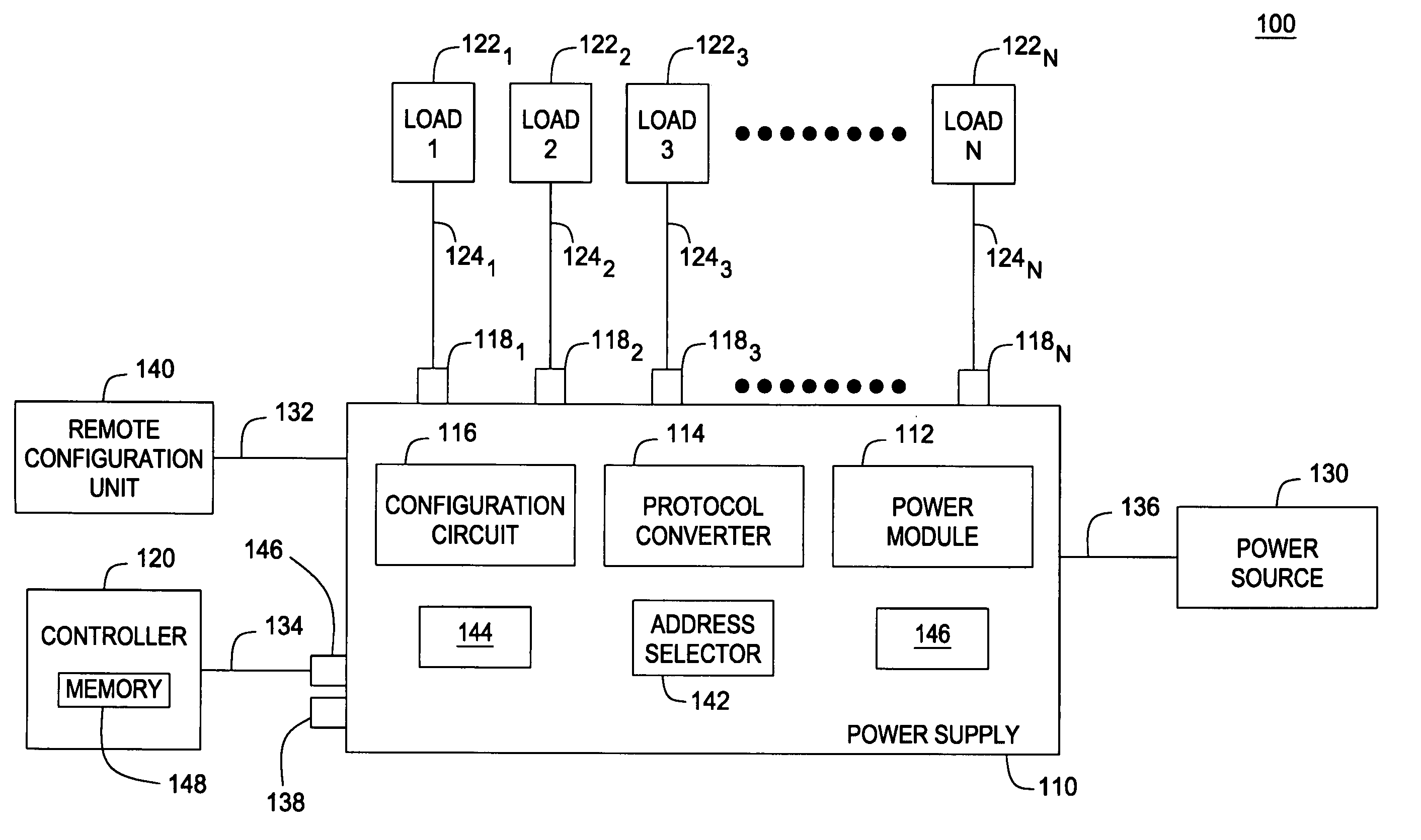
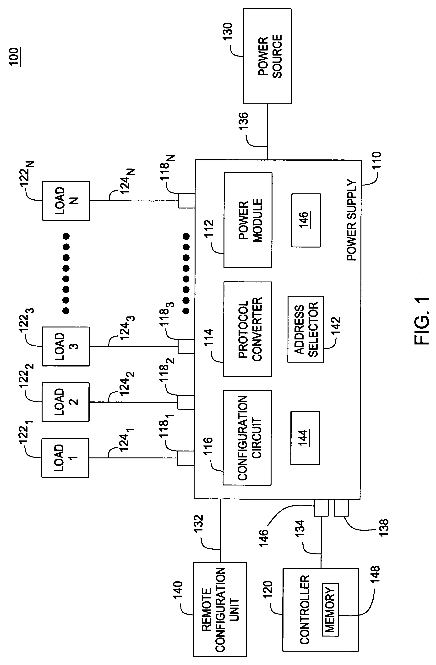
[0015] Embodiments of the present invention are generally directed to a power supply system and a method for operating electronically controllable loads used in entertainment lighting applications. Such applications may include theater, concert, museum, motion picture, television, sport event, public gathering, cruise ship, casino, amusement park lighting applications, and the like.

[0016] In the context of the present invention, the terms “controllable load” and “load” are used interchangeably in reference to lighting and effect devices used in the lighting applications and include stationary and moving luminaries, dimmers, stepper motors, fog / smoke generators, and the like. Hereafter, similar lighting and effect devices and power and data interfaces are identified using the same numeric references, except that suffixes may be added, when appropriate, to differentiate such devices and interfaces.

[0017]FIG. 1 is a high-level schematic diagram depicting a power supply system 100 for...


PUM


Abstract

A system and a method for operating devices (e.g., luminaries, light dimmers, effect devices, stepper motors, and the like) used in entertainment lighting applications is disclosed. Embodiments include a power supply operating a plurality of such devices coupled to selectively addressable outputs and having a converter of an industry-standard communication protocol (e.g., DMX512, RDM, or ACN protocol) in a communication protocol compatible with such devices.

Description

CROSS-REFERENCE TO RELATED APPLICATIONS [0001] This application claims benefit of U.S. provisional patent application Ser. No. 60 / 582,695 filed Jun. 24, 2004, the entirety of which is herein incorporated by reference.BACKGROUND OF THE INVENTION [0002] 1. Field of the Invention [0003] Embodiment of the present invention generally relate to entertainment lighting systems and, in particular, to methods and apparatus for powering devices used in entertainment lighting applications. [0004] 2. Description of the Related Art [0005] Lighting systems used in entertainment applications such as stage shows, sport events, public gatherings, and the like have grown into complex and elaborate systems using broad varieties of stationary and moving lighting and effect devices. [0006] In recent years, many lighting and effect devices have been computerized to improve functionality, operational performance, and serviceability of such systems. However, diversity and incompatibility of proprietary comm...

Claims


Application Information

Patent Timeline
29 Dec 2005
Publication
US20050289279A1
IPC
G06F13/36; H05B37/02
CPC
H05B37/0254; H05B47/18
Inventors
FAILS, GARY; DUNN, LAUREN E.