
Apparatus to suppress ascending gas flow and method for exhaust control thereof

Inactive Publication Date: 2006-01-05
SAMSUNG ELECTRONICS CO LTD
View PDF4 Cites 8 Cited by
  • Summary
  • Abstract
  • Description
  • Claims
  • Application Information

AI Technical Summary

Benefits of technology

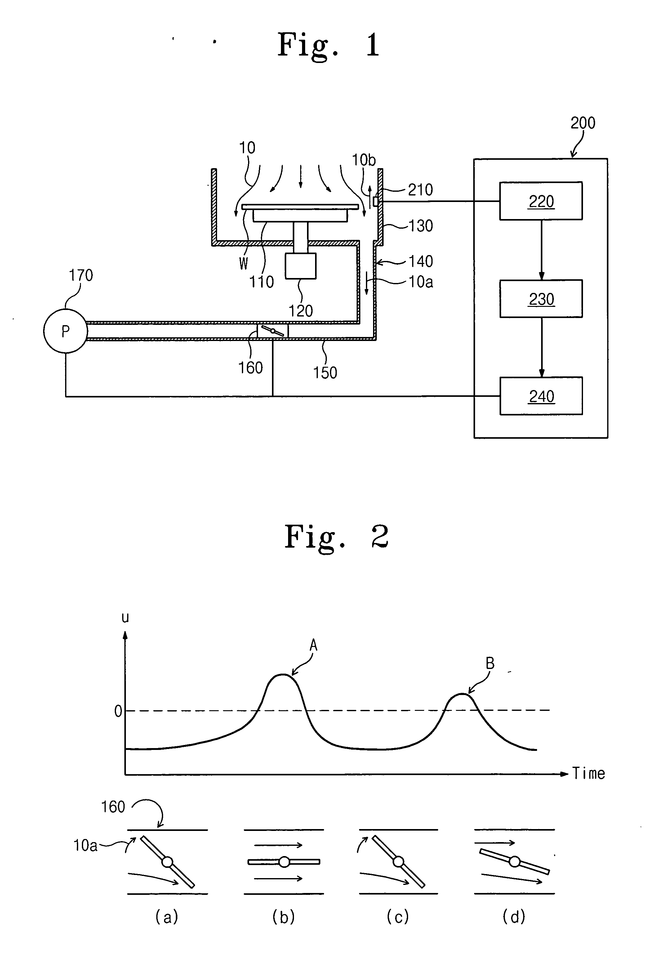
[0017] According to another example, non-limiting embodiment of the invention, a control unit may include a controller. The controller may adjust an exhaust flow rate from a vessel based on a detected direction of a gas flow in the vessel. The exhaust flow rate

Problems solved by technology

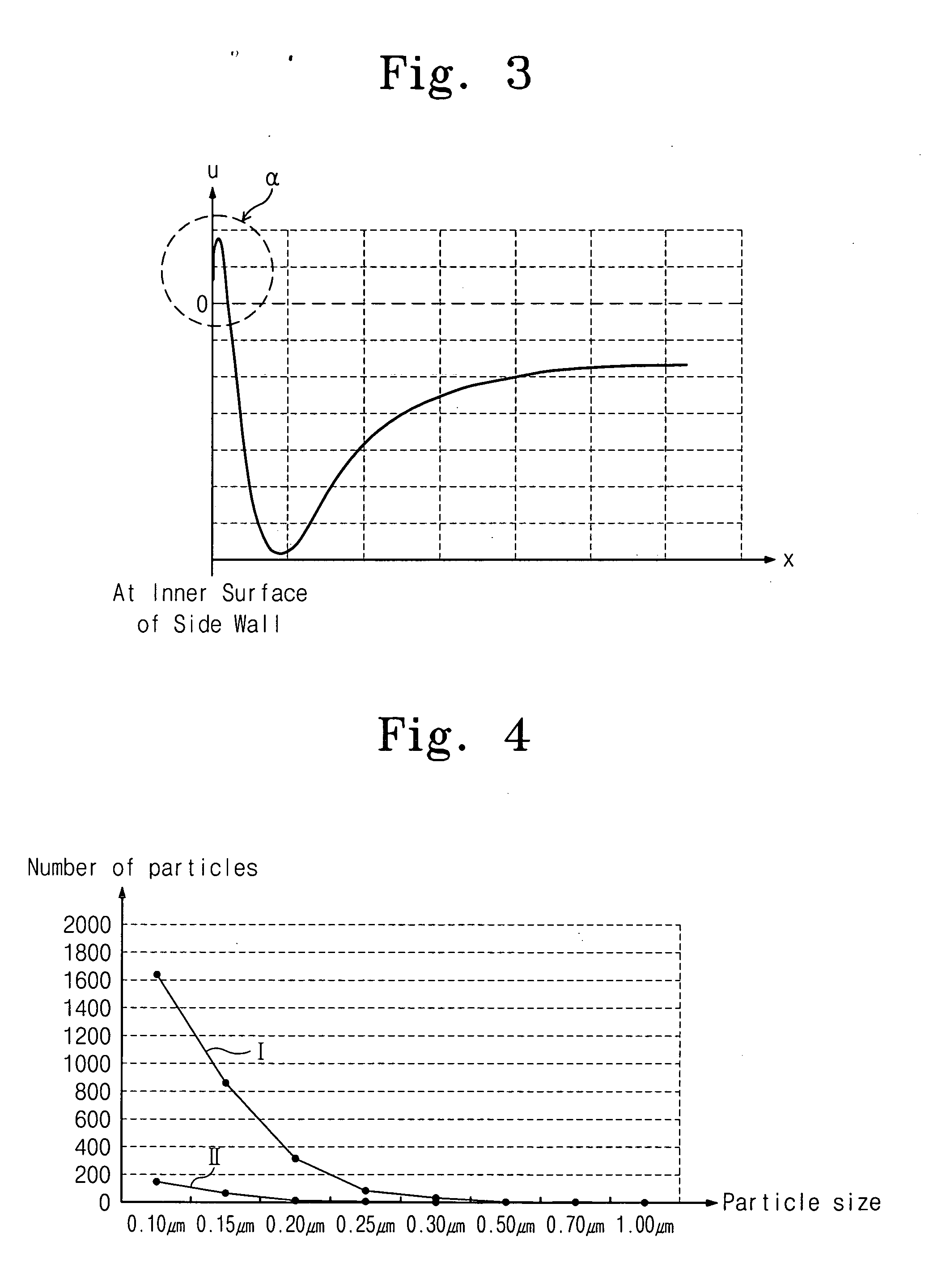
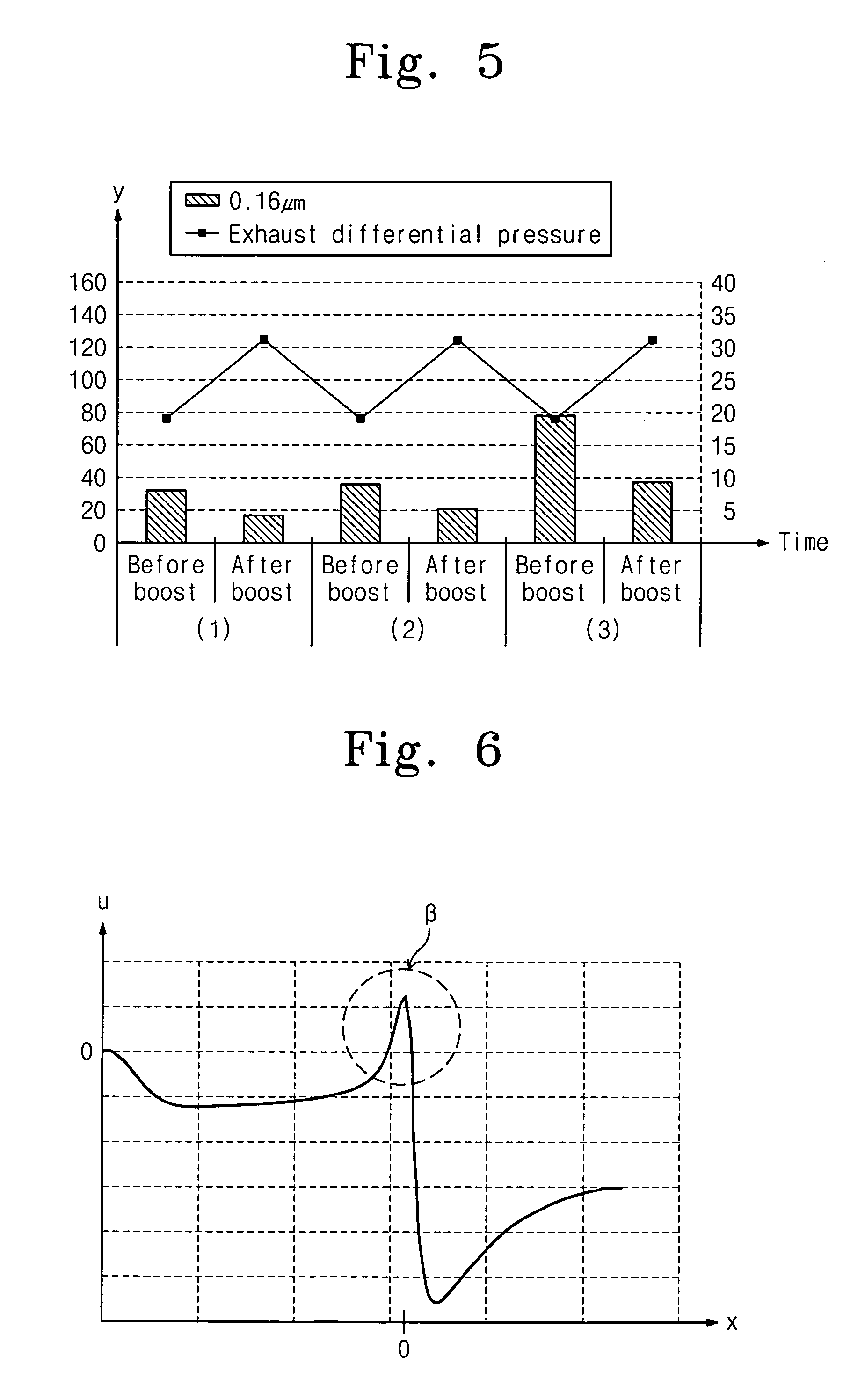
It has been reported that an ascending gas flow may be generated when a descending gas flow is driven between a bowl wall and a substrate lateral surface, and an exhaust differential pressure is insufficient.
For example, conventional techniques offer no countermeasure to control particles generated by an ascending gas flow that may be generated when a substrate is rotated at a relatively high speed.

Method used


Image

  • Apparatus to suppress ascending gas flow and method for exhaust control thereof
  • Apparatus to suppress ascending gas flow and method for exhaust control thereof
  • Apparatus to suppress ascending gas flow and method for exhaust control thereof

Examples


Embodiment Construction

[0025] Example, non-limiting embodiments of the present invention will now be described more fully with reference to the accompanying drawings. The invention may, however, be embodied in different forms and should not be construed as limited to the example embodiments set forth herein. Rather, the disclosed embodiments are provided so that this disclosure will be thorough and complete, and will fully convey the scope of the invention to those skilled in the art. The principles and features of this invention may be employed in varied and numerous embodiments without departing from the scope of the invention.

[0026] Well-known structures and processes are not described or illustrated in detail to avoid obscuring the present invention.

[0027] An element is considered as being mounted (or provided) “on” another element when mounted (or provided) either directly on the referenced element or mounted (or provided) on other elements overlaying the referenced element. Throughout this disclos...


PUM


Abstract

An apparatus and method for exhaust control. The apparatus may include a vessel to accommodate a gas flow of a gas, a sensor mounted on the vessel to sense a direction of the gas flow in the vessel, a conduit coupled to the vessel to exhaust the gas from the vessel, and a control unit that adjusts a flow rate of the gas through the conduit based on the direction of the gas flow in vessel sensed by the sensor. The method may include providing a gas flow of a gas in a vessel, sensing a direction of the gas flow in the vessel, exhausting the gas from the vessel at an exhaust flow rate, and adjusting the exhaust flow rate based on the sensed direction of the gas flow in the vessel.

Description

PRIORITY STATEMENT [0001] This U.S. non-provisional application claims priority under 35 U.S.C. §119 from Korean Patent Application No. 2004-51178, filed on Jul. 1, 2004 in the Korean Intellectual Property Office, the disclosure of which is incorporated herein in its entirety by reference. BACKGROUND [0002] 1. Field of the Invention [0003] The present invention relates in general to a semiconductor manufacturing apparatus and, more particularly, to a spin process apparatus that may suppress generation of particles while rotating a substrate and an exhaust control method of the spin process apparatus. [0004] 2. Description of Related Art [0005] The manufacture of semiconductor devices may involve a spin process that may be used, for example, to apply a photoresist coating, perform wet cleaning and / or perform wafer drying. Some efforts have been made to control the exhaust of a gas that may be used during a spin process. Such exhaust control techniques may enhance a completion of the ...

Claims


Application Information

Patent Timeline
IPC IPC(8): B01J8/04
CPCH01L21/67017H01L21/67034H01L21/67253H01L21/6715H01L21/67051H01L21/304
Inventor CHOI, HYUNG-SEOKHWANG, JUNG-SUNGPARK, KYOUNG-HOKO, KIL-SUNOH, YONG-WOON
Owner SAMSUNG ELECTRONICS CO LTD
Learn More