Self-propelled cleaner and suspension mechanism

a self-propelled cleaner and suspension mechanism technology, which is applied in the direction of suction cleaners, construction, applications, etc., can solve the problems of reduced mechanical malfunctions attributed to manufacturing and assembly errors are easy to be generated, and the self-propelled cleaner cannot be properly implemented. , to achieve the effect of increasing the ground contact properties of drive wheels

Inactive Publication Date: 2006-01-12
FUNAI ELECTRIC CO LTD
View PDF0 Cites 25 Cited by
  • Summary
  • Abstract
  • Description
  • Claims
  • Application Information

AI Technical Summary

Benefits of technology

[0009] The present invention provides a self-propelled cleaner and a suspension mechanism which damp properly impact applied to the drive wheels and increase the ground contact properties of the drive wheels relative to the traveling surface.

Problems solved by technology

In the case of the suspension mechanisms disclosed in JP-A-2003-033310 and JP-A-2004-016385, however, there has been caused a problem that the damping of the vertical motions of the drive wheels relative to the self-propelled cleaner which occur during the traveling thereof cannot be implemented in a preferred fashion, and hence the traveling of the self-propelled cleaner cannot be implemented properly.
Namely, in the case of the suspension mechanism disclosed in JP-A-2003-033310, since a drive unit is configured rotatably about a rotational shaft provided forward of drive wheels in an advancing direction of the self-propelled cleaner, mechanical malfunctions attributed to manufacturing and assembling errors tend to be generated easily, and the ground contact properties of the drive wheels are reduced, whereby the self-propelled cleaner cannot travel properly.

Method used


Image

  • Self-propelled cleaner and suspension mechanism
  • Self-propelled cleaner and suspension mechanism
  • Self-propelled cleaner and suspension mechanism

Examples


Embodiment Construction

[0019] Embodiments of the present invention will be explained with reference to the drawings hereinafter.

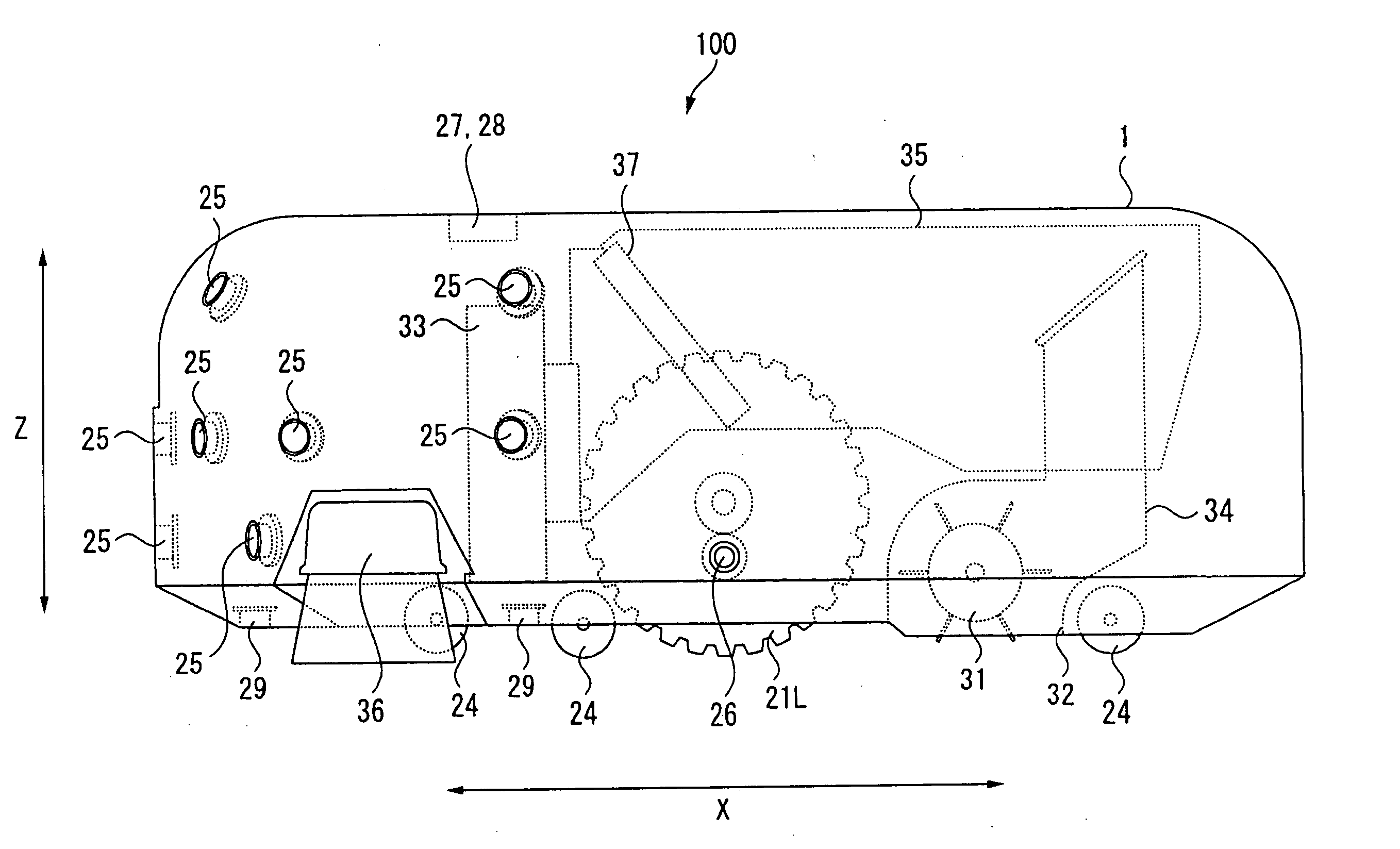
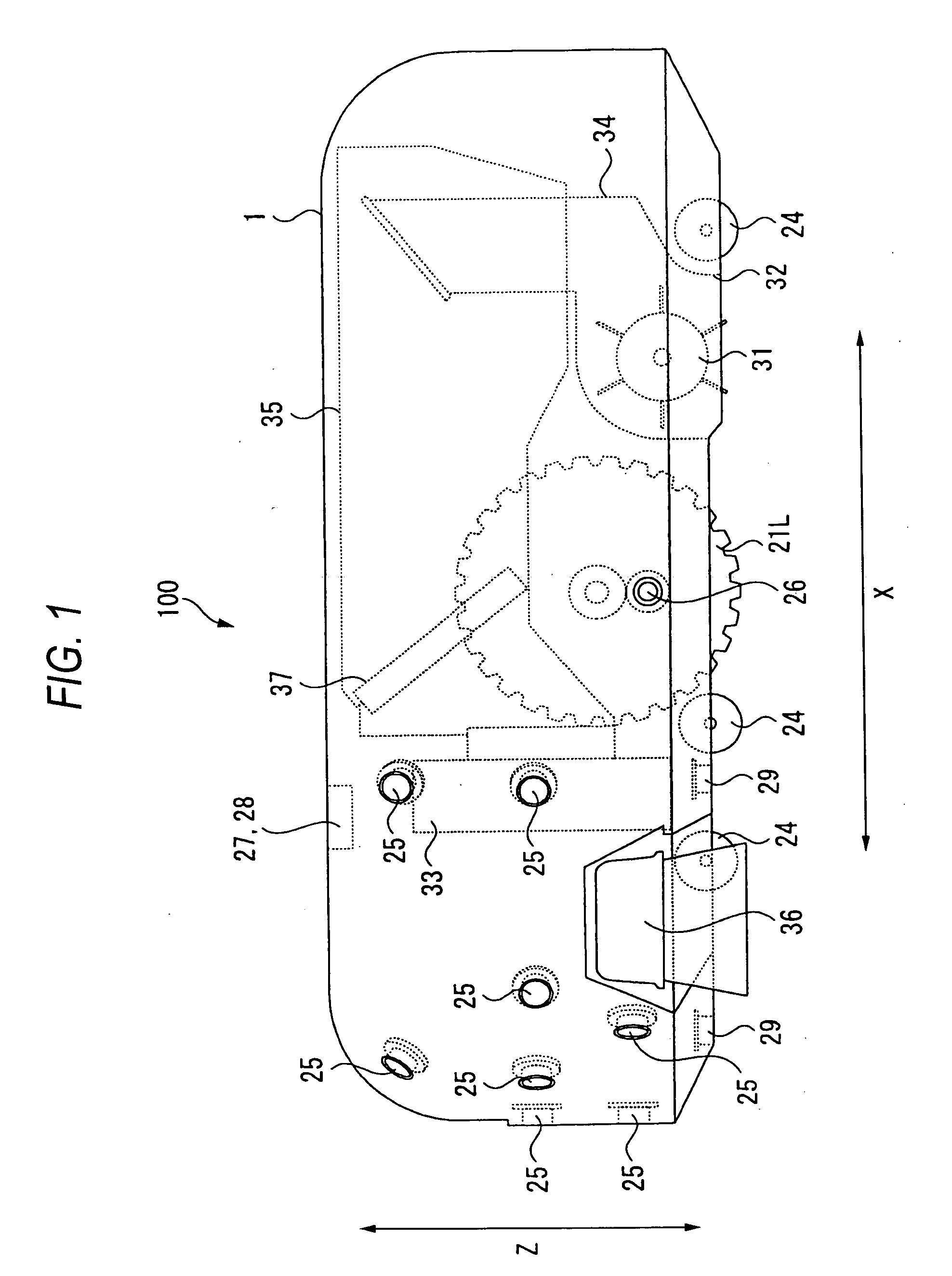
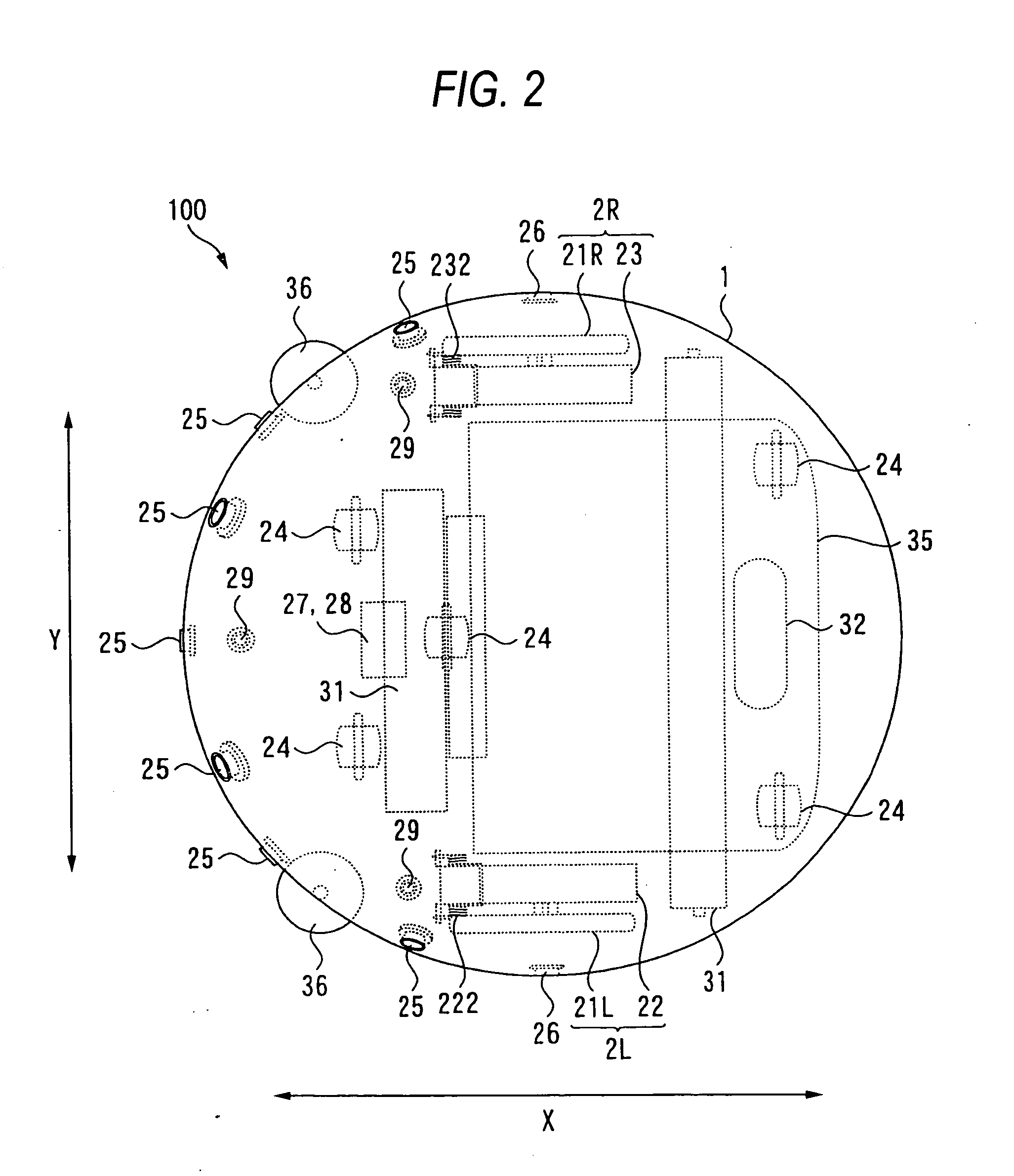
[0020]FIG. 1 is a side view of a self-propelled cleaner which will be illustrated as a preferred embodiment to which the invention is applied, resulting when the self-propelled cleaner is viewed from a side thereof, FIG. 2 is a plan view showing the self-propelled cleaner, and FIG. 3 is a front view of the self-propelled cleaner. In addition, FIG. 4 is a block diagram illustrating the configuration of a main part of the self-propelled cleaner.

[0021] Note that in FIGS. 1 to 3, states within a housing 1 of a self-propelled cleaner 100 are shown which would result when the interior of the housing were seen through the housing, and respective constituent elements provided within the housing 1 are to be shown by broken lines.

[0022] In addition, in the following description, a direction along a traveling direction of the self-propelled cleaner 100 is regarded as a longitudinal direc...


PUM


Abstract

A suspension mechanism includes: a drive unit that includes the drive wheel, a drive source for rotating the drive wheel, and a transmission mechanism that transmits a driving force of the drive source to the drive wheel, being integrally provided with each other; a supporting member that supports the drive unit and is fixedly mounted on the cleaner main body; a biasing member that biases the drive unit towards a traveling surface of the self-propelled cleaner; a first and a second linking members that connects the drive unit to the supporting member at two different points, respectively.

Description

BACKGROUND OF THE INVENTION [0001] 1. Field of the Invention [0002] The present invention relates to a self-propelled cleaner which performs cleaning by traveling autonomously and a suspension mechanism for a drive wheel that is provided on the self-propelled cleaner. [0003] 2. Description of the Related Art [0004] Conventionally, there have been known self-propelled cleaners that perform cleaning by traveling autonomously based on predetermined traveling patterns in rooms. [0005] The self-propelled cleaner of this type has, for example, two drive wheels which are provided along a direction which intersects with a traveling direction thereof at right angles and is adapted to perform cleaning a traveling surface such as a floor while traveling in predetermined directions by driving the drive wheels so provided. [0006] As the self-propelled cleaners, there have been known self-propelled cleaners having a suspension mechanism for damping vertical motions of the drive wheels relative to...

Claims


Application Information

Patent Timeline
Patent Type & Authority Applications(United States)
IPC IPC(8): E01H1/08
CPCA47L2201/04A47L9/009
Inventor UEHIGASHI, NAOYA
Owner FUNAI ELECTRIC CO LTD
Why Eureka
Try Eureka