
Method and adaptive modulation in multi-carrier communication

a multi-carrier communication and adaptive modulation technology, applied in multi-frequency code systems, channel coding adaptation, signalling characterisation, etc., can solve the problem of additionally required control signals

Inactive Publication Date: 2006-01-12
HITACHI LTD
View PDF5 Cites 49 Cited by
  • Summary
  • Abstract
  • Description
  • Claims
  • Application Information

AI Technical Summary

Benefits of technology

This patent describes a way to adjust the type of data transmitted over different parts of a network based on their signal strength. It allows for more efficient use of resources by only sending necessary information about which part of the network needs what kind of transmission. Overall, this results in faster and better communication between devices.

Problems solved by technology

This patent discusses two methods for improving wireless communication: one involves using multiple signals or symbols to transmit more information, while another focuses on adjusting the way these signals are sent based on the quality of the network connection. However, both approaches have their limitations. For example, the use of multiple signals may require extra controls between devices to ensure they agree on how to send the information, whereas adjusting the sending approach too much can result in slowed down performance if there are sudden changes in channel quality. The technical problem addressed in this patent is finding ways to improve efficiency and reliability in wireless communications without requiring excessive control measures.

Method used


Image

  • Method and adaptive modulation in multi-carrier communication
  • Method and adaptive modulation in multi-carrier communication
  • Method and adaptive modulation in multi-carrier communication

Examples


first embodiment

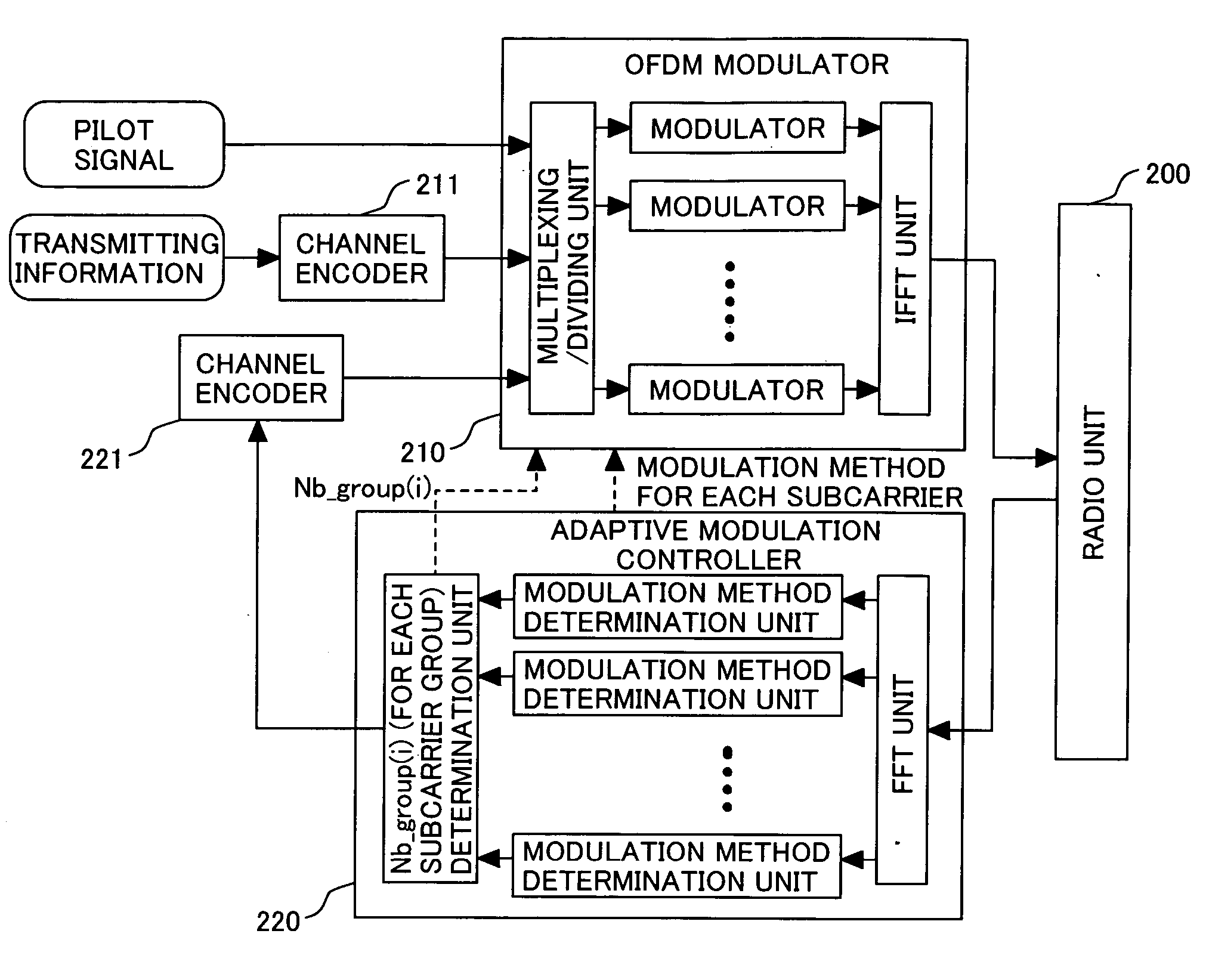
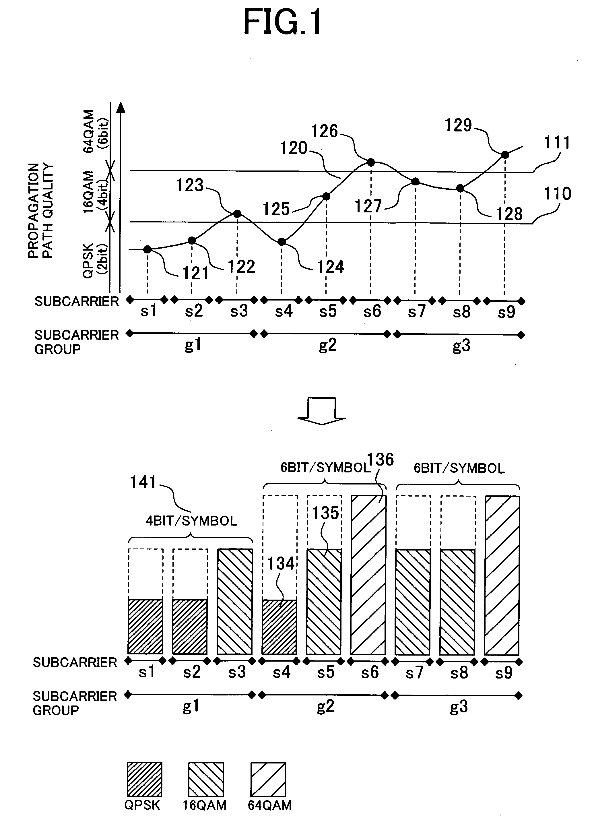
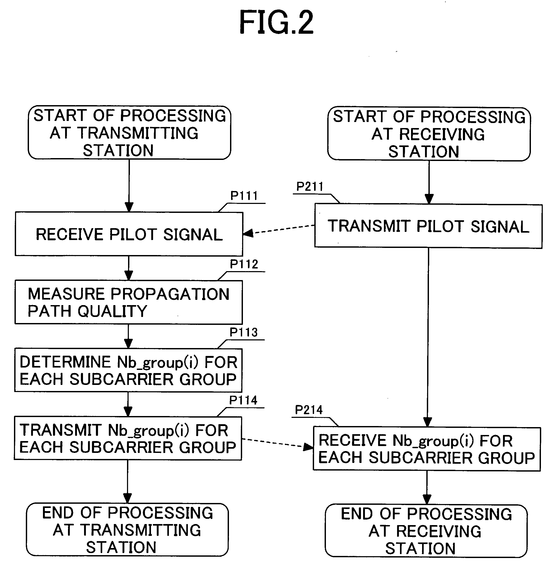
[0035] In an adaptive modulation method of a first embodiment according to the present invention, firstly a transmitting station identifies the quality 120 of a propagation path for communication. As a means by which a transmitting station identifies the propagation path quality 120, either the transmitting station may directly measure the quality of a propagation path or the transmitting station may be notified from a receiving station of the quality measured by the receiving station.

[0036] Next, a transmitting station employing an adaptive modulation method according to the present invention determines a modulation method for each subcarrier. In the selection of a modulation method for each subcarrier, the modulation method is selected so as to have the larger number of communicable bits per symbol according as the propagation path quality 120 of each subcarrier improves. For example, in the case of FIG. 1, on the basis of the thresholds 110 and 111, QPSK is selected when the prop...

second embodiment

[0048] In this case, in the adaptive modulation method of the second embodiment according to the present invention, firstly the receiving station identifies the quality 120 of a propagation path for communication. As a means by which a receiving station identifies a propagation path quality 120, either the receiving station may directly measure the propagation path quality or the receiving station may be notified from a transmitting station of the quality measured by the transmitting station.

[0049] Next, the receiving station employing an adaptive modulation method according to the present invention determines a modulation method for each subcarrier. In the selection of a modulation method for each subcarrier, the modulation method is selected so as to have a larger number of communicable bits per symbol according as the propagation path quality 120 of each subcarrier improves. For example, in the case of FIG. 1, on the basis of the thresholds 110 and 111, QPSK is selected when the ...


PUM


Abstract

In a radio-communication system and a radio station, one or more subcarriers are grouped, and the maximum bit number per symbol of the modulation method used for each subcarrier is determined for each group and shared between a transmitting station and a receiving station. The transmitting station divides and allocates a coded signal to subcarriers in accordance with the bit number per symbol, modulates each of the allocated signals by a predetermined modulation method, and transmits the modulated signals. The receiving station demodulates the received signal by the predetermined modulation method, adds a signal having zero likelihood when the bit number per symbol of a modulation method for demodulation is different from a maximum bit number, and decodes the demodulated signal by summarizing the demodulated results.

Description


Claims


Application Information

Patent Timeline
Owner HITACHI LTD
Learn More