Centrifugal separator

a centrifugal separator and centrifugal technology, applied in the direction of centrifuges, rotary centrifuges, heat, etc., can solve the problems of difficult to completely maintain a sterile state, and achieve the effect of difficult centrifugal action

Inactive Publication Date: 2006-01-12
EPPENDORF HIMAC TECH CO LTD
View PDF6 Cites 31 Cited by
  • Summary
  • Abstract
  • Description
  • Claims
  • Application Information

AI Technical Summary

Benefits of technology

[0016] However, according to the centrifugal separating apparatus 1′ of the background art shown in FIG. 14 and FIG. 15, there is needed an operation of taking out the rotor 13 from the chamber 12, disassembling and sterilizing the rotor 13, thereafter, integrating the sterilized rotor 13 again to integrate into the chamber 12 and thereafter, connecting the pipe 108 to the rotor 13 and therefore, in the operation, there is a possibility of mixing bacteria or the like floating in the atmosphere to a path of the sample (hereinafter, referred to as ‘sample line’), sterilizing cannot be carried out in a state of integrating the rotor 13 and therefore, it is difficult to centrifugally separate the sample in a state of maintaining a sterile state.

Problems solved by technology

Further, also the sample injecting apparatus 100′ is disintegrated and thereafter integrated after sterilizing parts forming the sample line and the parts are connected to the rotating apparatus portion 10 and therefore, it is very difficult to completely maintain a sterile state.

Method used


Image

  • Centrifugal separator
  • Centrifugal separator
  • Centrifugal separator

Examples


embodiment 1

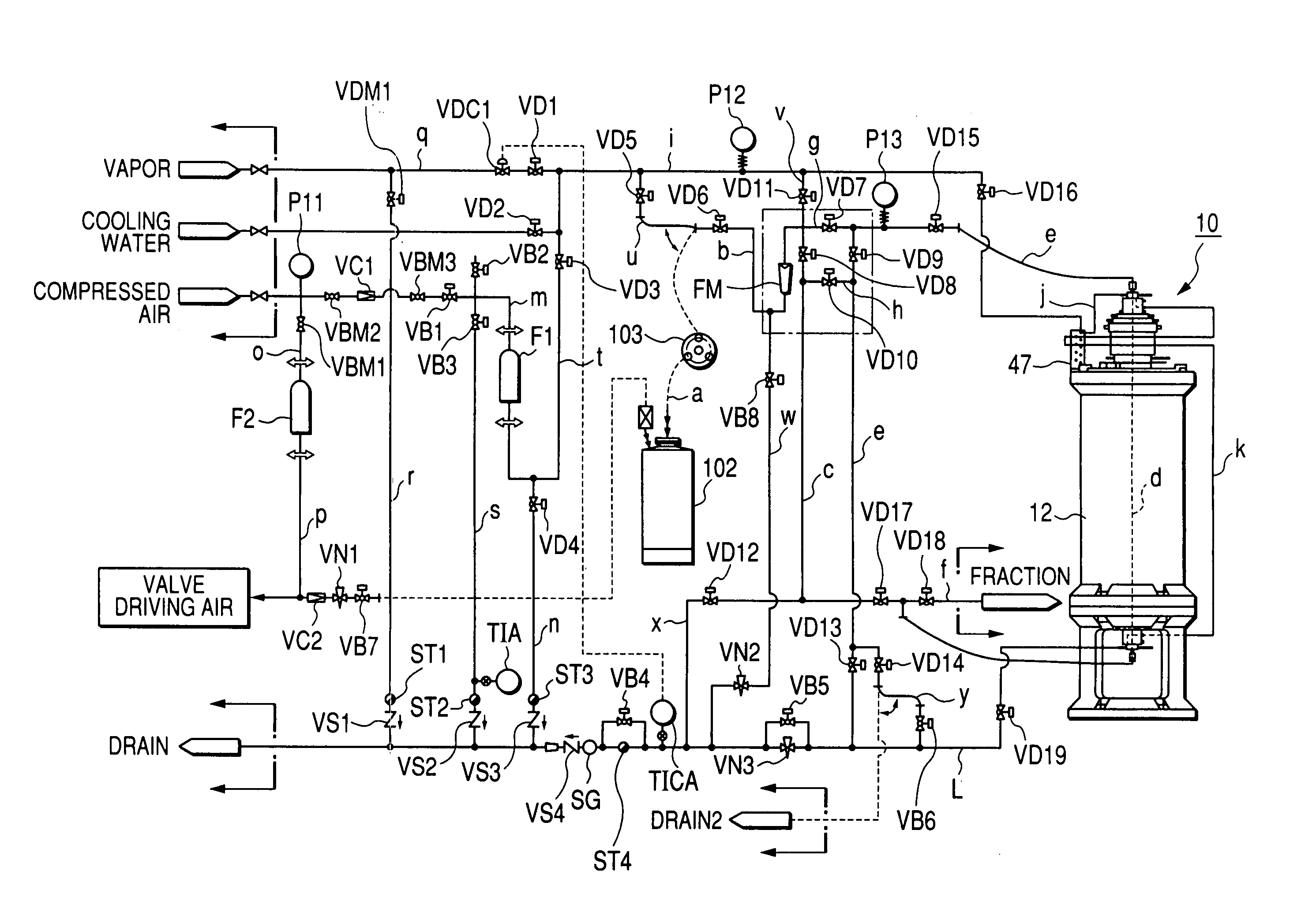
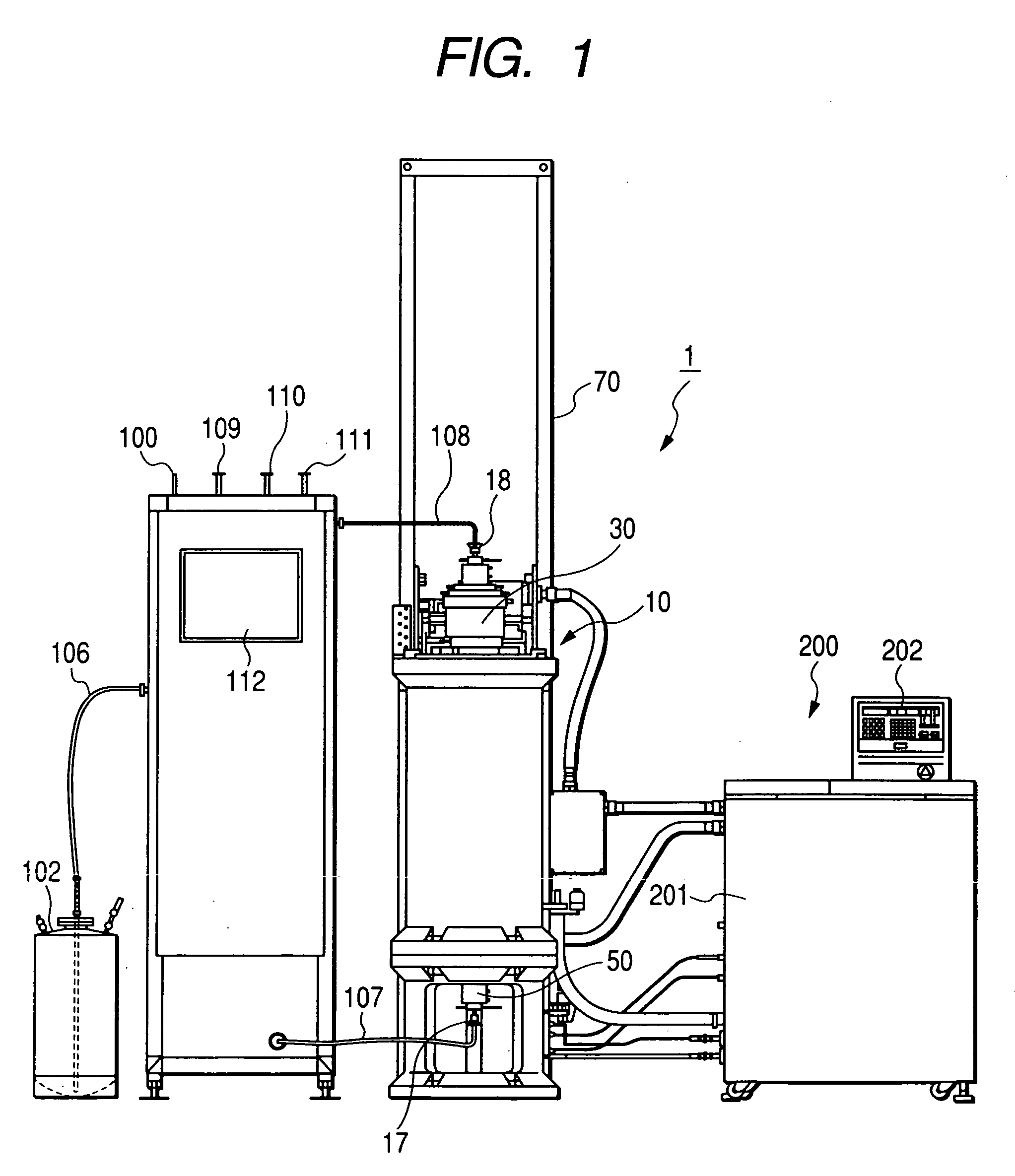
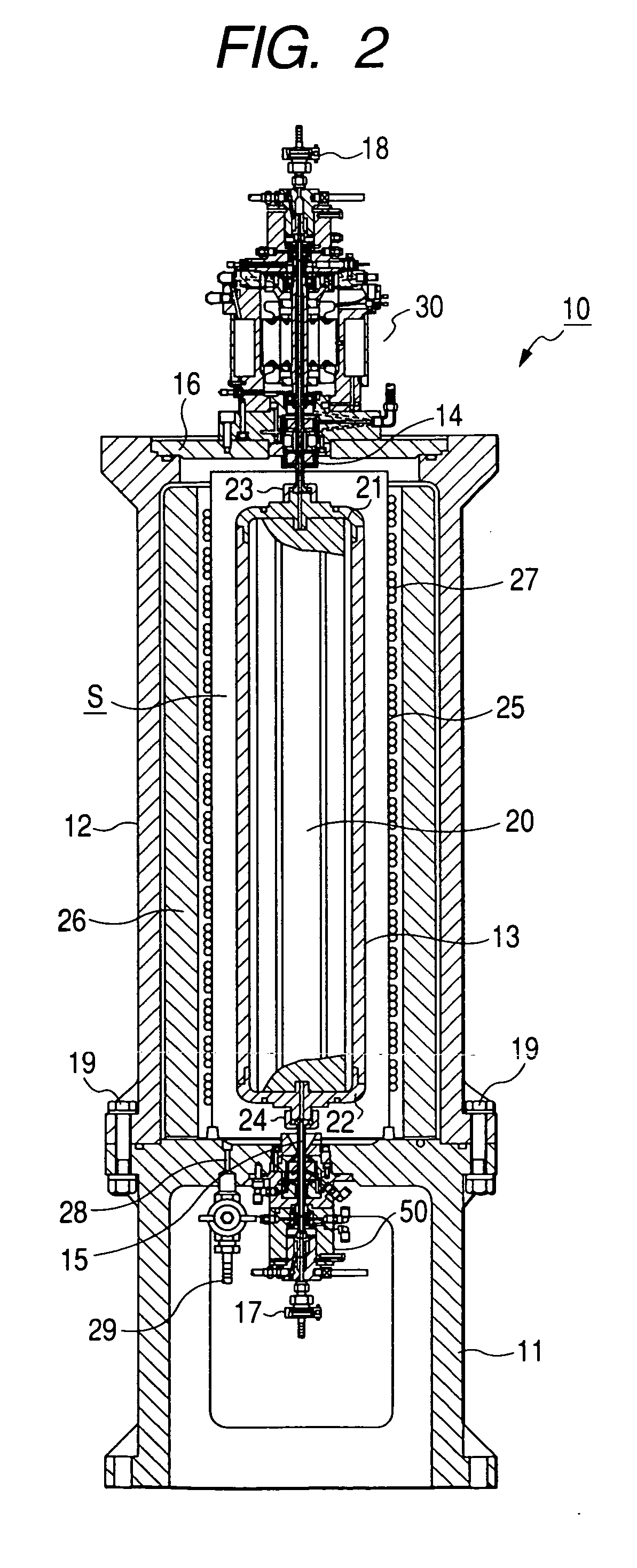
[0037]FIG. 1 is a front view of a centrifugal separator according to Embodiment 1 of the invention.

[0038] Although first, a total constitution of a centrifugal separator 1 according to the invention will be explained in reference to FIG. 1, the centrifugal separator 1 according to the invention is constructed by a constitution similar to that of the centrifugal separator 1′ of the background art except that a vapor sterilizing apparatus 100 is constituted by integrating sterilizing means to the sample injecting apparatus 100′ of the centrifugal separator 1′ of the background art shown in FIG. 14 and FIG. 15 and therefore, in FIG. 1, elements the same as those shown in FIG. 14 and FIG. 15 are attached with the same notations and hereinafter, an explanation thereof at a second time will be omitted.

[0039] The vapor sterilizing apparatus 100 shown in FIG. 1 is constituted independently from the rotating apparatus portion 10 and the control apparatus portion 200 for controlling the rot...

embodiment 2

[0104] Next, Embodiment 2 of the invention will be explained in reference to FIG. 12 and FIG. 13.

[0105] The embodiment is characterized in adopting a constitution of circulating cooling water in a closed loop in the centrifugally separating step, and other constitution is similar to that of Embodiment 1, mentioned above.

[0106] That is, as shown by FIG. 12, a line z branched from the line i is connected to the line L, the cooling water line of a closed loop is constituted by the lines i, z, L and the lines j, k, a cooling water pump 90 is provided and a cooling water tank 91 arranged in a sterile chamber is connected to middles of the line z, and a cooling coil 92 is wound at a surrounding of the cooling water tank 91. Further, the cold medium supplied from the refrigerator, not illustrated, is made to flow in the cooling coil 92 and cooling water flowing in the cooling water line of the closed loop is cooled by evaporating the cold medium.

[0107] In the vapor sterilizing processin...


PUM


Abstract

A centrifugal separator includes: a sample line; and a rotating apparatus portion including a rotor that has a rotor chamber. The centrifugal separator centrifugally separates a sample by supplying the sample from the sample line into the rotor and driving to rotate the rotor in the rotor chamber and discharges the centrifugally separated sample from the rotor via the sample line. The centrifugal separator includes: a sterilizing apparatus for sterilizing at least a portion with which the sample is brought into contact by making a sterilizing fluid flow through the sample line.

Description

BACKGROUND OF THE INVENTION [0001] 1. Field of the Invention [0002] The present invention relates to a centrifugal separator for centrifugally separating a sample at inside of a rotor rotated at high speed in a rotor chamber. [0003] 2. Background Art [0004]FIG. 14 and FIG. 15 show a background art of a centrifugal separator of this kind. [0005] That is, FIG. 14 is a front view of a centrifugal separator of a background art, FIG. 15 is a side view showing operation of attaching and detaching a rotor in the centrifugal separator, and a centrifugal separator 1′ of the illustrated example is constituted by a rotating apparatus portion 10, a sample injecting apparatus 100′ and a control apparatus portion 200 arranged on both sides thereof as shown by FIG. 14. [0006] The rotating apparatus portion 10 is provided with a chamber 12 in a cylindrical shape on a base 11 fixed onto a floor face 2 by a plurality of pieces of bolts 3, and a rotor 13 in a cylindrical shape shown in FIG. 15 is rota...

Claims


Application Information

Patent Timeline
Patent Type & Authority Applications(United States)
IPC IPC(8): B04B15/02B04B15/06B04B15/08
CPCA61L2/07A61L2/18B04B15/02B04B7/00B04B15/00B04B1/02B04B15/06
Inventor TOBITA, YOSHINORIAIZAWA, MASAHARUAKATSU, KATSUNORIKOIZUMI, TOMOHIRO
Owner EPPENDORF HIMAC TECH CO LTD
Why Eureka
Try Eureka