Process for manufacturing plate electrode stackings

Inactive Publication Date: 2006-01-19
AMER SIL
View PDF2 Cites 2 Cited by
  • Summary
  • Abstract
  • Description
  • Claims
  • Application Information

AI Technical Summary

Benefits of technology

[0012] The object of the present invention is therefore to provide a process for manufacturing a plate electrode stacking for use in battery assembly, which allows a simplified, efficient and more economical procedure, while ensuring safe and high quality assembly. A further object of the invention is to provide a separator material for use in such a process.

Problems solved by technology

Known processes often require manual steps or very complex automation equipment to manufacture protected plate electrodes or electrode stackings for use in battery assembly.
Prior art methods are either labor intensive and time consuming, implying partially manual procedures, or require complex and expensive equipment to automate the numerous cutting, folding, wrapping, assembling and sealing steps.

Method used


Image

  • Process for manufacturing plate electrode stackings
  • Process for manufacturing plate electrode stackings
  • Process for manufacturing plate electrode stackings

Examples


Embodiment Construction

[0042] The abovementioned and further objects of the present invention will be more apparent from the following description of a not limiting embodiment with reference to the attached drawings.

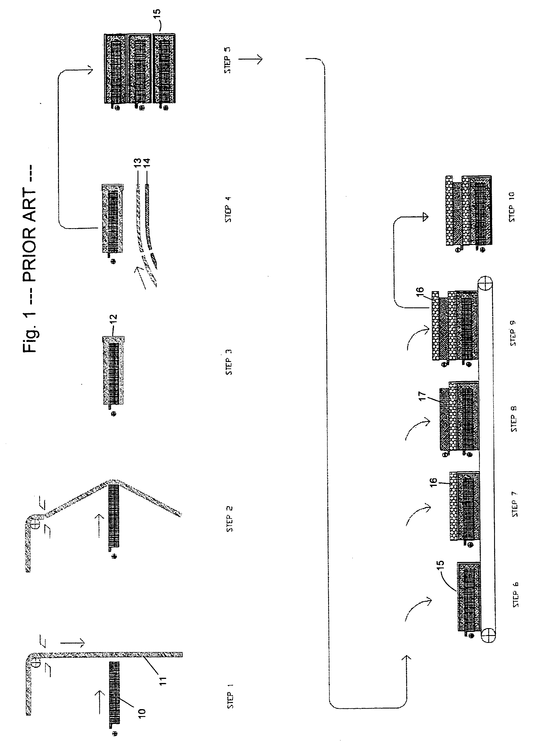
[0043] In FIG. 1, which represents a prior art process for the manufacture of electrode plate stackings, the positive plates 10 are placed onto an assembly belt.

[0044] In step 1, the Hydramatic 11 is unrolled vertically and taken by the advancing plates 10 in the middle. The Hydramatic 11 is cut to size and U-wrapped around the plate 10 in step 2. In step 3, the Hydramatic 11 is fixed with a clip to the bottom of the plate 10 by forming and mounting a cap or boot 12. In step 4, the glass mat 14 and the Koroseal 13 are unrolled beneath the chain conveyor, heat sealed together on an inline hot roller, then cut on a rotary knife against a back-up roll. This cut laminate is then positioned below the Hydramatic 11 and guided with “tooth jigs” on the main conveyor. The folding around the edges is ...


PUM

PropertyMeasurementUnit
Thicknessaaaaaaaaaa
Shapeaaaaaaaaaa

Abstract

A process for manufacturing of a plate electrode stacking for use in batteries, comprising the steps of supplying a separator material comprising a polymer sheet layer with an overlapping portion and a glass mat layer, placing a positive plate electrode onto the glass mat layer, folding and wrapping this separator material around the positive plate electrode, attaching an overlapping portion to form a sleeved plate electrode, and placing a negative plate electrode onto the sleeved positive plate electrode.

Description

BACKGROUND OF THE INVENTION [0001] The present invention relates to a process for manufacturing plate electrode stackings for use in electrochemical cells, such as batteries, and a separator material for use in such a process. [0002] Lead acid batteries are widely used and include adjacent positive and negative electrodes immersed in an electrolyte and spaced by separators. [0003] The electrodes used in the manufacture of such batteries are generally made of lead dioxide for the positive electrode and lead for the negative electrode. The electrodes are separated from each other by a battery separator that prevents the adjacent electrodes from coming into physical contact and that provides space for an electrolyte. [0004] Two different lead acid battery designs are used commercially: the flooded cell and the recombinant cell. [0005] In a flooded cell, only a small portion of the electrolyte is absorbed into the separator. Thus, the battery separator typically has ribs extending from ...

Claims


Application Information

Patent Timeline
IPC IPC(8): H01M2/16H01M2/18H01M50/451H01M50/466
CPCH01M2/1606H01M2/1686H01M2/18Y10T29/49108H01M10/14H01M2004/024Y02E60/126H01M10/125Y02E60/10H01M50/44H01M50/451H01M50/466
Inventor LAMBERT, URBAIN
Owner AMER SIL
Why Eureka
Try Eureka