Coupling plate for stacking lottery ticket dispensers

a lottery ticket dispenser and stacking technology, applied in the field of stacking plates, can solve the problems of not being able to be easily removed from the dispenser, not designed to be conveniently arranged in an interchangeable stacking relationship,

Inactive Publication Date: 2006-01-26
SCHAFER SYST
View PDF9 Cites 15 Cited by
  • Summary
  • Abstract
  • Description
  • Claims
  • Application Information

AI Technical Summary

Problems solved by technology

Because fabricated dispensers do not include molded engagement means therein, they are not designed to be conveniently arranged in an interchangeable stacked relationship.
Instead, such dispens

Method used


Image

  • Coupling plate for stacking lottery ticket dispensers
  • Coupling plate for stacking lottery ticket dispensers
  • Coupling plate for stacking lottery ticket dispensers

Examples


Embodiment Construction

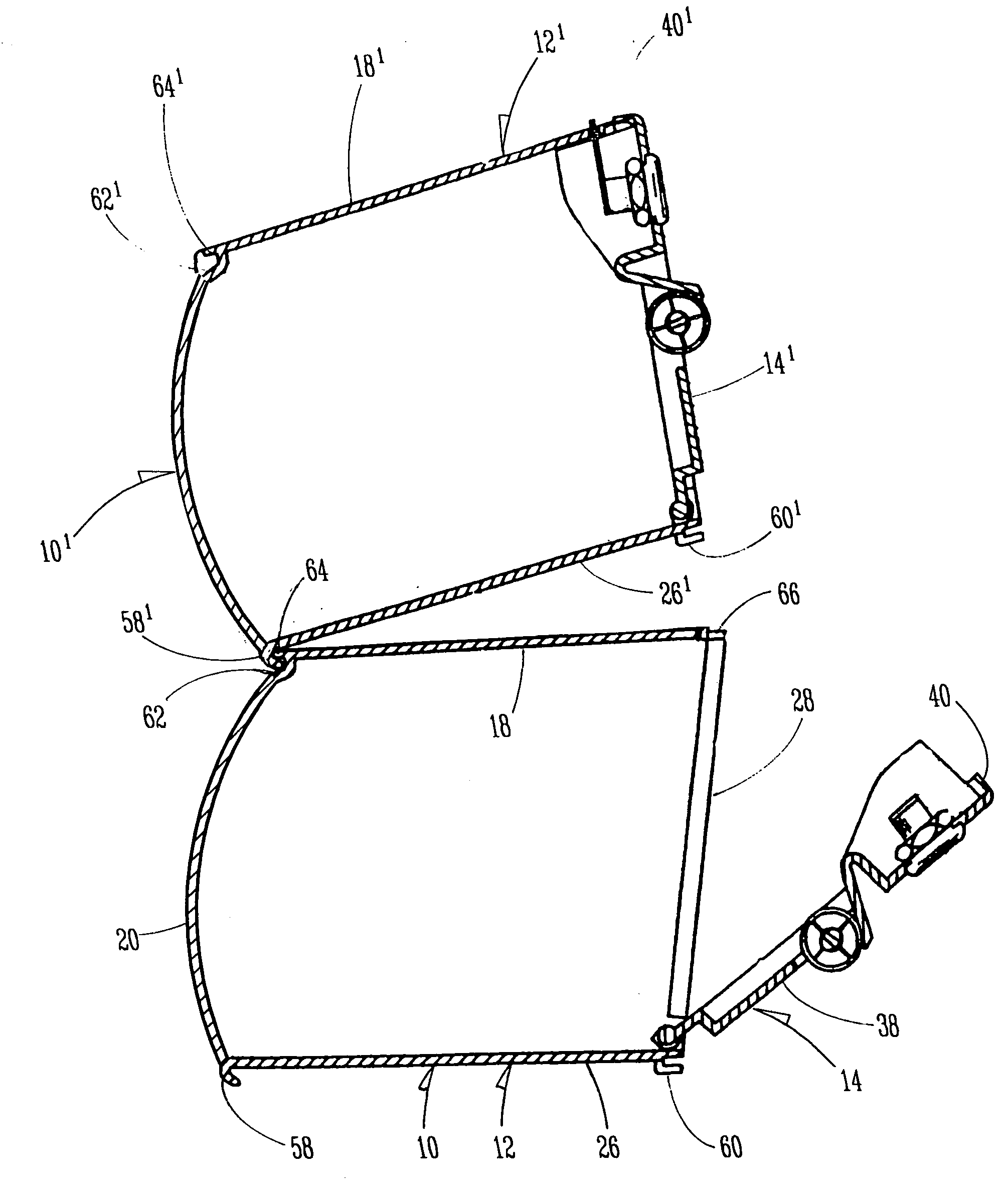
[0018] With reference now to the drawings, a dual modular hinged lottery ticket dispenser known in the prior art is shown in FIG. 1 indicated generally at 10 and includes a box unit 12 and a door 14.

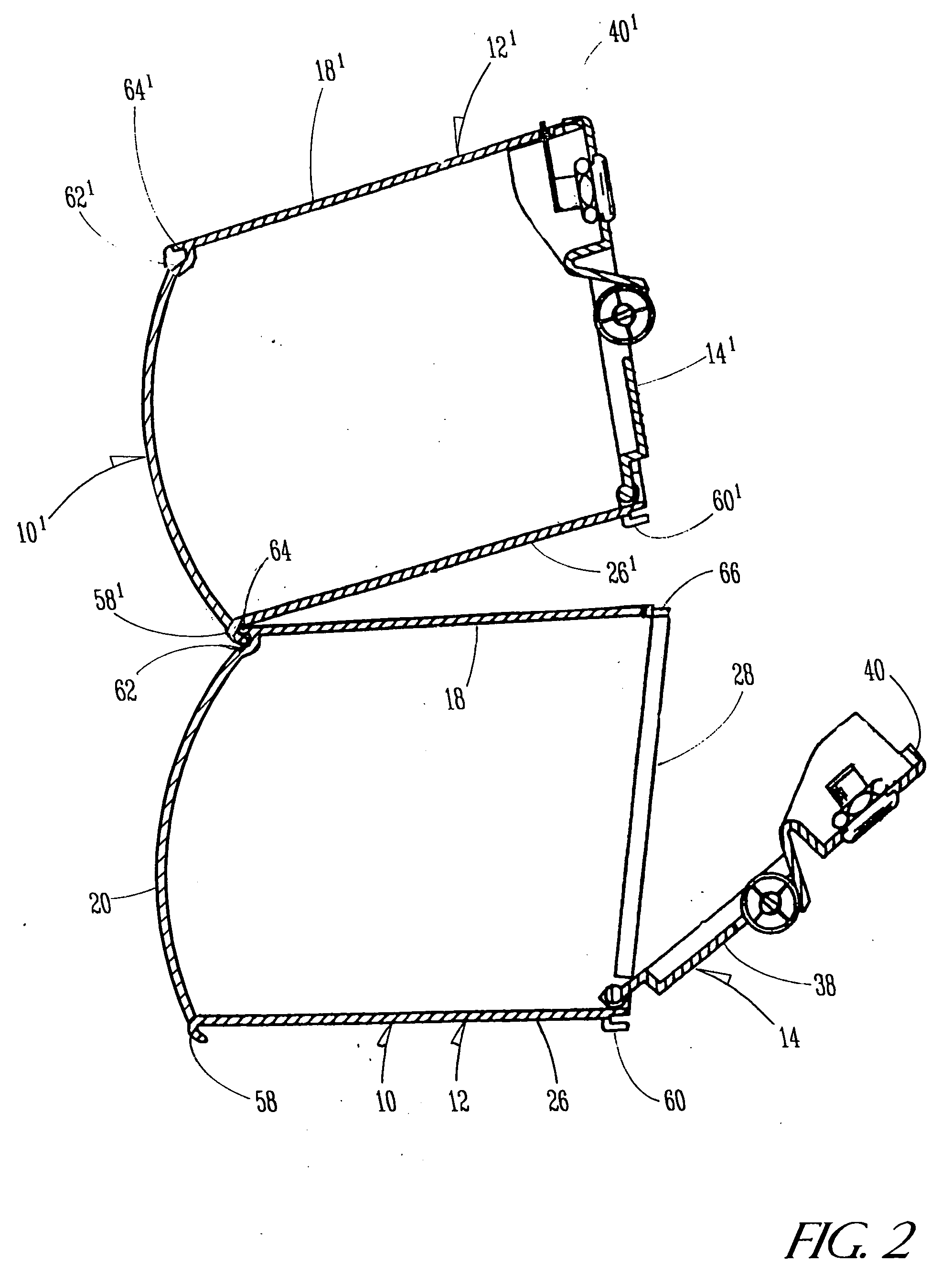
[0019] The box unit 12 has a top surface 18, a front wall 20, a pair of opposite side walls 22 and 24, a bottom surface 26 and a rear opening 28 (see FIG. 2) that allows access to the inside of the unit 12. Located within the unit 12 is a divider portion 30 for forming two storage compartments, which are adapted for storing two stacks of lottery tickets in a side-by-side relationship.

[0020] The door 14 has a vertical face 38, a horizontal top flange 40 and a pair of vertical side flanges 42 and 44. A bottom portion 46 of the door 14 is generally cylindrical in shape and has a pair of cylindrical posts 48 and 50 at opposite ends. The posts 48 and 50 are designed to be receivably journaled in circular openings 52 in the sidewalls 22 and 24 to pivotally attach the bottom portion 46 of the...


PUM


Abstract

A coupling plate is provided to serve as a connecting member for stacking a fabricated ticket dispenser on top of a box-type molded dispenser in a semi-permanent relationship.

Description

BACKGROUND OF THE INVENTION [0001] 1. Field of the Invention [0002] The present invention relates in general to a structure that assists in the stacking of molded and fabricated lottery ticket dispensers. More particularly, this invention relates to a coupling plate that serves as an intermediate member for demountably attaching a fabricated ticket dispenser to the top of a molded dispenser. [0003] 2. Description of the Prior Art [0004] The use of stackable box-like structures for displaying and dispensing of lottery tickets has long been known in the art. Originally, the most common popular methods for attaching such structures in a stackable arrangement had been either permanent or not lockable. However, over a decade ago, a molded stackable display and dispensing structure was developed to include engagement means on the top of the structure that were adapted to co-act with engagement means on the bottom of a second similarly shaped structure for attachment in a stacked and locke...

Claims


Application Information

Patent Timeline
IPC IPC(8): G07F11/00
CPCG07B3/04G07F17/42G07F9/10
Inventor JENSEN, CRAIG A.
Owner SCHAFER SYST
Why Eureka
Try Eureka