

Device for viewing stereoscopic images on a display
- Summary
- Abstract
- Description
- Claims
- Application Information
AI Technical Summary
Benefits of technology
Problems solved by technology
Method used
Image

Examples
first embodiment
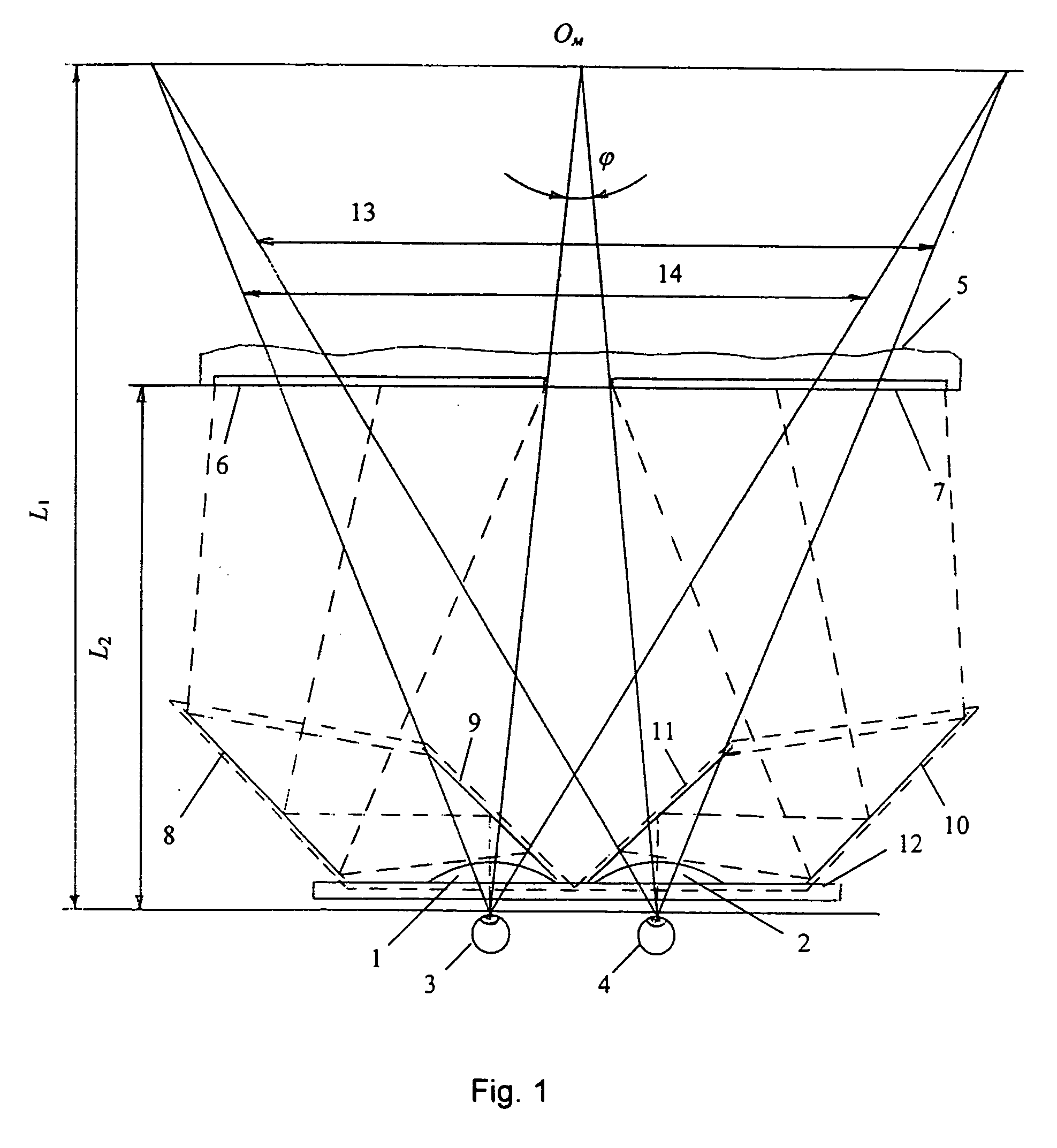
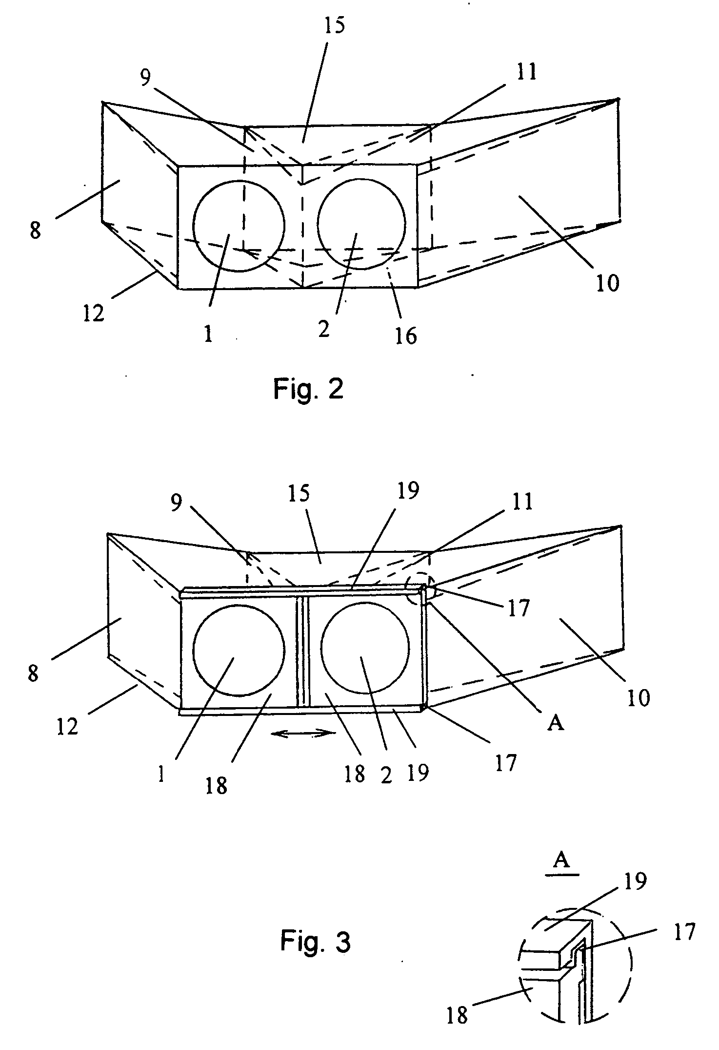
[0082] Another implementation of the first embodiment is a device (see FIG. 4), in which the magnifying lenses (1,2) and corresponding mirror pairs (8,9 and 10,11 in FIG. 1) are two identical optical modules (20 and 21) with fixed mutual positioning of lenses and mirrors. To ensure the mirror symmetry of the mirror pairs relative to the vertical symmetry plane of the lenses (1,2), orthogonal to their optical axes' plane, the modules (20, 21) will be mounted onto the main frame (12) with one module (21) turned to the other (20) at a 180° angle about the axis of its magnifying lens (2). In the particular case of this implementation (see FIG. 5), the modules (20, 21) are positioned on the main frame (12) to ensure horizontal adjustment to the distance between the centers of the viewer's eyes, which in this case can be achieved by way of the ribbed (22) flanges (23) on the module side facing the viewer, and the reference slots (24) on the main frame (12).
[0083] The following description...
second embodiment
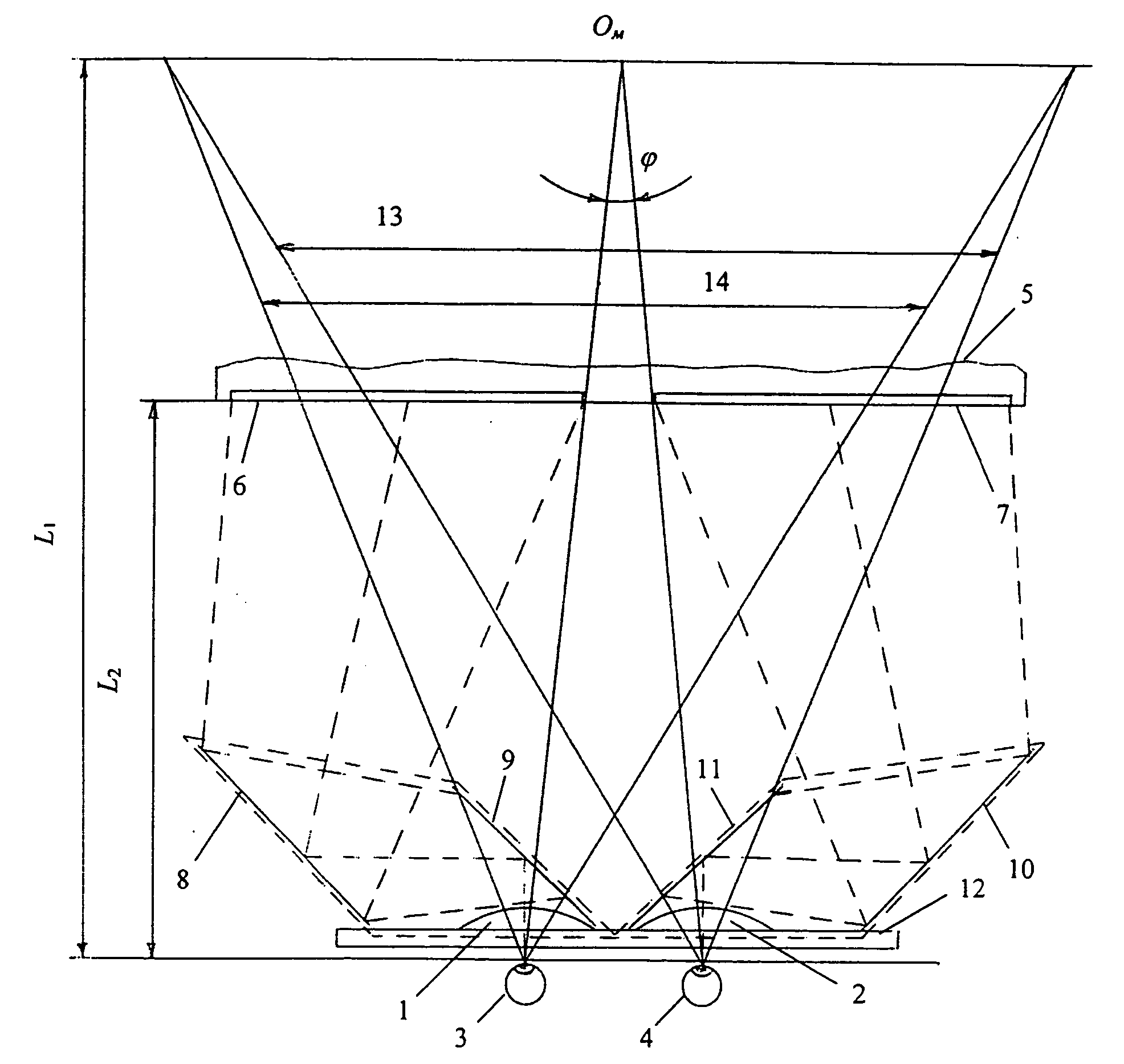
[0088] In the implementation of the invention shown in FIG. 10, the left (8, 9) and right (10, 11) mirror pairs are positioned so that the optical axes A1 and A2 of the upper and lower stereopair images directed from the video display screen to the mirrors 8,10 lie in a plane that is a vertical symmetry plane of the imaginary picture lying at a virtual distance L1. The axes pass through the geometrical centers of the upper (47) and lower (48) video-displayed (5) stereopair images. This case ensures the highest quality of perceived stereoimage viewing, because in the viewer's perception, not only are the centers superimposed, but so are the borders of the stereopair images.
[0089] In the general case of the second embodiment of the invention, the optical axes directed from the eyes through the lens and mirror pairs to the upper and lower stereopair images, may lie outside the vertical symmetry plane of the imaginary picture in the regions between the outside mirrors and stereopair ima...
third embodiment
[0099] An important specific implementation of the third embodiment is a device distinctive in that the modules' (59, 60, see FIG. 15) side facing the viewer contains a square mounting frame (62) with correspondingly ribbed edges (63, 64) and a rectangular main frame with grooves (65) matching those edges, thus allowing for adjustment of the optical modules at a distance corresponding to the centers of the viewer's eyes. To allow viewing of stereoscopic images video-displayed as left and right images, the optical modules (59, 60) can be positioned on the main frame (61) when the edges (63) of the fixing frame (62) are inserted into the grooves (65) on the main frame (61); the edges are located symmetrically on different sides of the modules' symmetry plane. The planes of the optical axes—the modules' symmetry planes—are set in a horizontal plane (see FIG. 15a). The edges (63) of the modules (59, 60) are affixed to the main frame (61), with one module turned at a 180° to the other, t...
PUM
 Abstract
Description
Claims
Application Information