
Method and apparatus for controlling convergence distance for observation of 3D image

a technology of convergence distance and 3d image, which is applied in the field of methods and apparatus for controlling convergence distance for observation of 3d images, can solve the problems of easy fatigue of eyes, and increasing the amount of data to process

Inactive Publication Date: 2006-02-09
SAMSUNG ELECTRONICS CO LTD
View PDF0 Cites 56 Cited by
  • Summary
  • Abstract
  • Description
  • Claims
  • Application Information

AI Technical Summary

Benefits of technology

[0016] The present invention provides a method and an apparatus for controlling a convergence distance for observation of a 3-D image, in which a guide image sequentially moved, photographed, and played back and forth of a convergence distance of an observer by a convergence distance controller so that an observer can easily find a position point at which an object image is displayed by controlling a convergence distance using the guide image.

Problems solved by technology

Despite an excellent sense of reality provided by a 3-D image, such an apparatus is not widely distributed because there is a problem that eyes are easily fatigued when seeing a 3-D image.
However, in everyday life a person moves his or her face or eyes to freely see a desired place and the adjusting the convergence distance to the image set in advance becomes a very unnatural circumstance, giving a great burden to the eyes.
Further, since a current convergence point of a user should be ascertained in real time through the head's position and the eyeball image, the amount of data to process is increased, whereby a system is complicated.
In the meantime, since an eyeball should be fixed to a predetermined point so that a 3-D image may be observed effectively for a long time, an eyesight fatigue problem is generated.

Method used


Image

  • Method and apparatus for controlling convergence distance for observation of 3D image
  • Method and apparatus for controlling convergence distance for observation of 3D image
  • Method and apparatus for controlling convergence distance for observation of 3D image

Examples


Embodiment Construction

[0036] The present invention will now be described more fully with reference to the accompanying drawings, in which exemplary embodiments of the invention are shown.

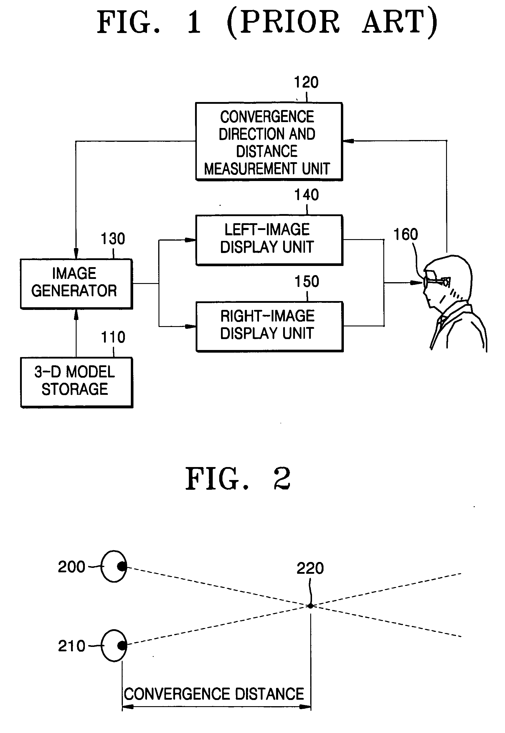
[0037]FIG. 2 is a view illustrating a convergence distance using eyeballs and a convergence point.

[0038] Referring to FIG. 2, a convergence means that convergence lines from left and right eyeballs 200 and 210 are concentrated onto one point in the front. Here, a point at which both convergence lines meet is called a convergence point 220, and a distance between the eyeballs 200 and 210 on both sides and the convergence point 220 is called a convergence distance.

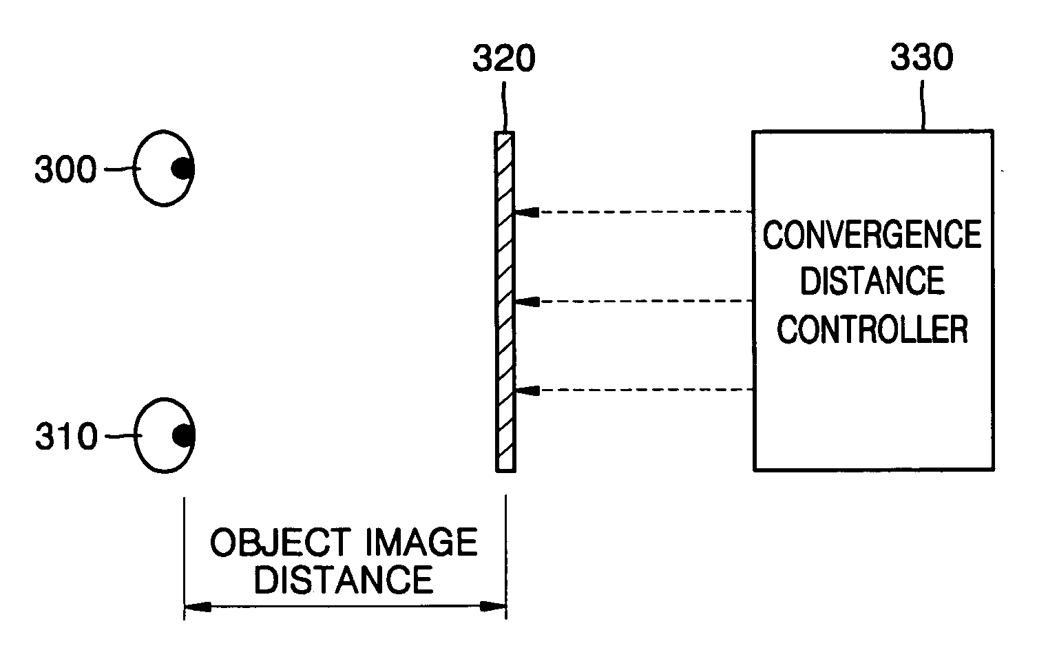
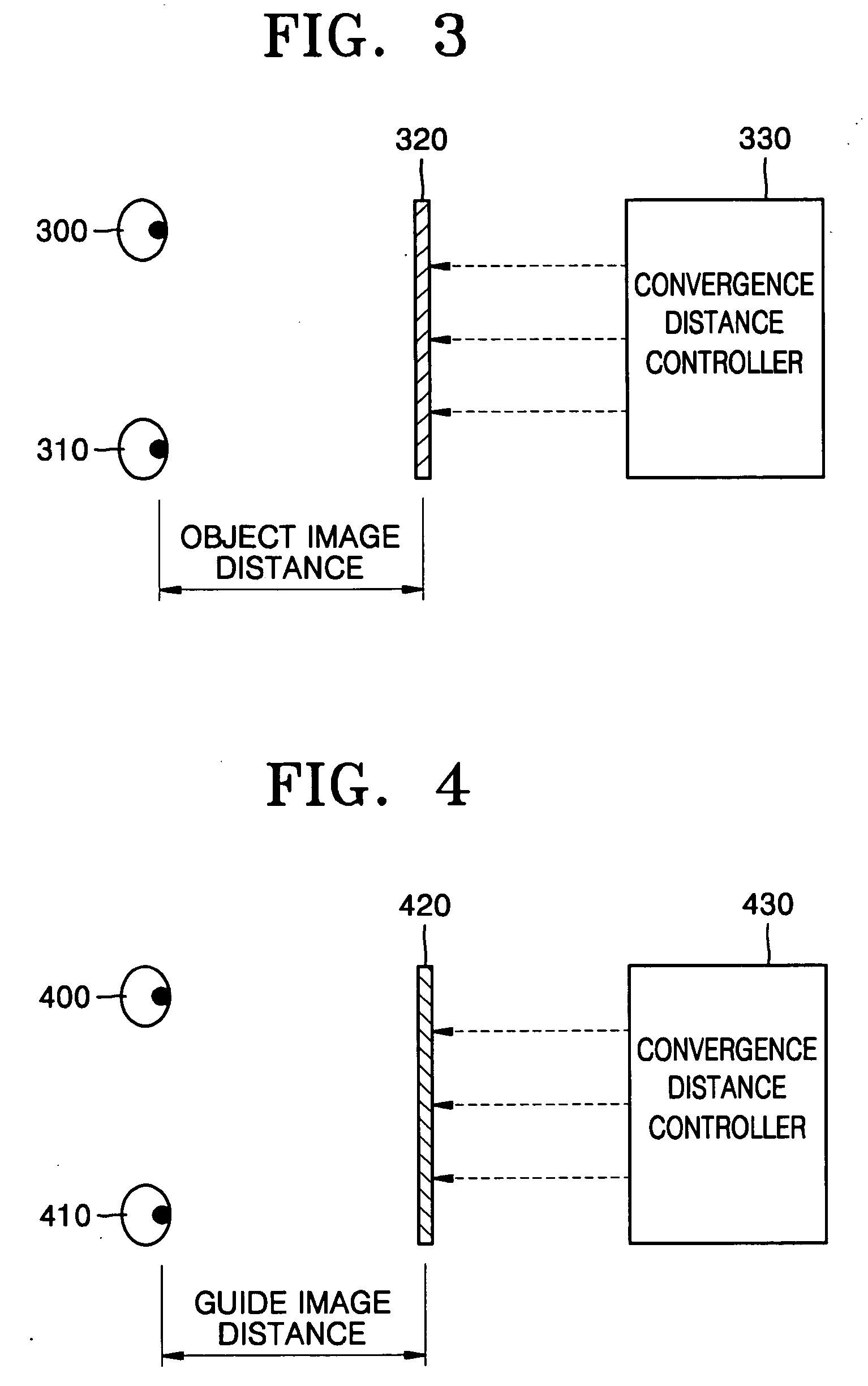
[0039]FIG. 3 is a view illustrating an object image distance.

[0040] Referring to FIG. 3, an object image 320, which is a virtual image realized by a convergence distance controller 330, means an image intended for being shown to an observer. For the object image, there exist a 3-D movie and a virtual reality.

[0041] The object image 320 is recognized as being...


PUM


Abstract

A method and an apparatus for controlling a convergence distance for observation of a 3-D image are provided. The apparatus includes an object image storage, a guide image storage, an image synthesizer, and a controller. The object image storage stores object image data generated by photographing 3-dimensionally an object positioned at an object image point. The guide image storage stores guide image data generated by sequentially moving back and forth of the object image point and photographing 3-dimensionally a guide object. The image synthesizer receives the object image data and the guide image data to generate a synthesized image. The controller controls to sequentially output the guide image data and if a photographing distance of the guide image data coincides with an object image point, controls to stop the outputting of the guide image data so that a convergence distance of an observer may coincide with the object image point.

Description

BACKGROUND OF THE INVENTION [0001] This application claims the priority of Korean Patent Application No. 10-2004-0061093, filed on Aug. 3, 2004, in the Korean Intellectual Property Office, the disclosure of which is incorporated herein in its entirety by reference. [0002] 1. Field of the Invention [0003] The present invention relates to a method and an apparatus for controlling a convergence distance for observation of a 3-dimensional (3-D) image, and more particularly, to a method and an apparatus for easily realizing a cubic effect of a 3-D image without a separate head / eyeball movement detector for detecting a head / eyeball movement so as to ascertain a convergence distance of an observer, and without the inconvenience of wearing a separate display apparatus. Further, some methods and apparatus consistent with the invention reduce eyesight fatigue caused by inducing eyeball movement of an observer when observing an object image for a long time. [0004] 2. Description of the Related...

Claims


Application Information

Patent Timeline
IPC IPC(8): H04N13/00H04N15/00H04N13/239
CPCH04N13/0239H04N13/0402H04N13/0296H04N13/302H04N13/296H04N13/239G03B35/00
Inventor SOHN, JUN-ILBAE, SOO-HYUNCHO, JOON-KEELEE, SANG-GOOG
Owner SAMSUNG ELECTRONICS CO LTD
Learn More