Methods and systems for substrate surface evaluation

a substrate surface and evaluation technology, applied in the field of parts inspection methods and systems, can solve the problems of insufficient measurement of super-polished substrate surface quality, limited operator training, and inability to achieve the effect of achieving the effect of reducing the number of operators

Inactive Publication Date: 2006-02-09
HONEYWELL INT INC
View PDF7 Cites 1 Cited by
  • Summary
  • Abstract
  • Description
  • Claims
  • Application Information

AI Technical Summary

Benefits of technology

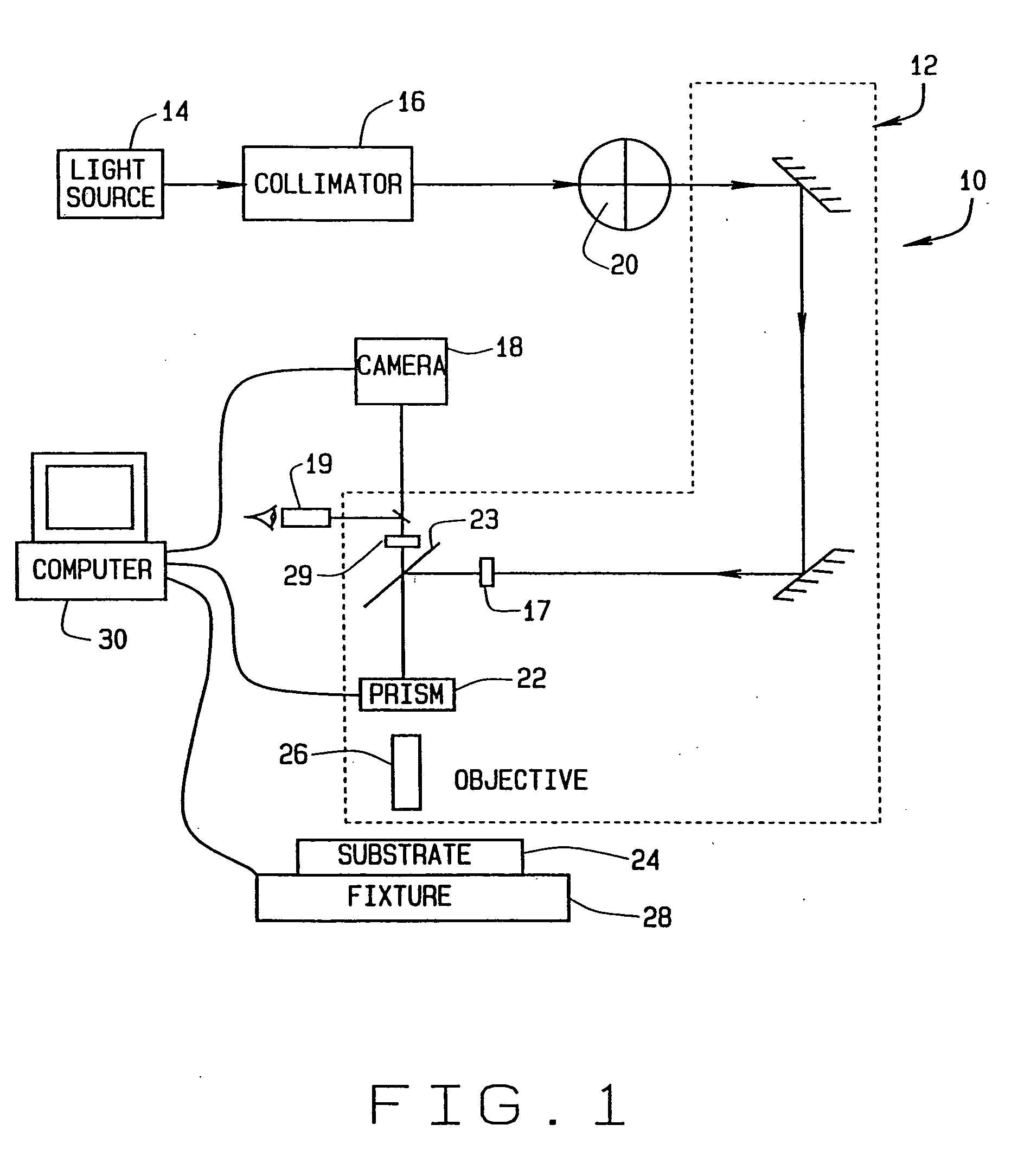
[0006] In another aspect, a substrate inspection system for determining a surface quality of substrate samples is provided. The system comprises a differential interference contrast microscope that includes an eyepiece, an eyepiece focus adjustment, a microscope focus adjustment, a reticule, a prism, an objective, a camera view, an eyepiece view, and a fixture for holding a substrate sample. The system further comprises a light source, a camera, and a computer for collecting data from the camera and microscope. The microscope can be switched between the eyepiece view and the camera view and the fixture allows adjusting the slope of a substrate sample to achieve a specified peak response ratio. The computer is configured to capture at least one image of the surface slope of the substrate sample, and process images of the surface slope to determine surface quality and reconstruct an approximate surface of the substrate sample.

Problems solved by technology

Currently, subjective inspection techniques are utilized for inspection of polished substrates and have been found inadequate for measuring super-polished substrate surface quality and maintaining processes for producing super-polished surfaces.
In one known inspection process, the resolution of the inspection is limited by an amount of operator training, operator patience, operator eyesight, as well as an optical configuration of the inspection system.
As such, consistent inspection quality is difficult to achieve.
However, evaluating the super-polish process by using the coated mirror products delays feedback to the substrate polishing process and is also subject to factors external to the polishing process.
Further, because the substrates are coated with the reflective compound prior to inspection, substrates with flawed surfaces may be coated which increases manufacturing costs as more costly pieces (i.e. the coated substrates) may have to be scrapped or reworked.

Method used


Image

  • Methods and systems for substrate surface evaluation
  • Methods and systems for substrate surface evaluation
  • Methods and systems for substrate surface evaluation

Examples


Embodiment Construction

[0014] While the present invention is herein described in the context of a specific application wherein the invention has been found to be particularly advantageous, it will be apparent to those skilled in the art that numerous variations or modifications may be made to the exemplary embodiments without departing from the spirit and scope of the present invention. It will further be apparent that the advantages of the present invention are applicable to other applications and environments. Consequently, the exemplary embodiments described herein are set forth for illustrative purposes only and are not intended to limit practice of the invention in any aspect. The system and method are not limited to the specific embodiments described herein. Components of each system and method can be practiced independently and separately from one another. Each system and method also can be used in combination with other components and methods.

[0015] The methods and systems described herein allow ...


PUM

PropertyMeasurementUnit
surface qualityaaaaaaaaaa
power spectral densityaaaaaaaaaa
frequencyaaaaaaaaaa

Abstract

A method for determining a surface quality of a substrate sample using a differential interference contrast microscope is described. The microscope includes an eyepiece, an eyepiece focus adjustment, a microscope focus adjustment, a light source, at least one of an aperture or reticule, a camera view, a prism and an eyepiece. The method includes calibrating the focus of the eyepiece with the focus of the camera and determining a peak response ratio for the microscope through adjustment of phase between differential beams of the microscope. The substrate sample is placed under the microscope, illuminated with the light source, and brought into focus with the microscope focus. Phase between differential beams is adjusted, at least one image of the substrate sample is captured and processed to determine a level of surface structure on the substrate sample.

Description

CROSS REFERENCE TO RELATED APPLICATIONS [0001] This application claims priority of Provisional Application Ser. No. 60 / 383,469 filed May 24, 2002.BACKGROUND OF THE INVENTION [0002] This invention relates generally to parts inspection methods and systems and, more particularly, to evaluation of highly polished substrate surfaces. [0003] Many optical devices, such as ring laser gyroscopes, include highly polished components, such as substrates utilized in making mirrors. Operation of such devices is greatly dependent upon the quality of the mirrors. For example, super-polish quality of a substrate surface, that is, a lack of scratches and other inconsistencies in the substrate surface, is one factor that determines the amount of light scattered from a polished substrate which has been coated with a reflective material. Currently, subjective inspection techniques are utilized for inspection of polished substrates and have been found inadequate for measuring super-polished substrate sur...

Claims


Application Information

Patent Timeline
Patent Type & Authority Applications(United States)
IPC IPC(8): G01B9/02G01N21/88G01B11/30G02B21/00
CPCG02B21/0016
Inventor FASHANT, DANIEL R.SAVARD, THOMAS A.SELLIN, TRACY L.ECKLUND, STEVEN P.
Owner HONEYWELL INT INC
Why Eureka
Try Eureka