
Micro-mixer

a micro-mixer and mixer technology, applied in the field of micro-mixers, can solve the problems that mechanical actuators or physical barriers can damage the structure of biological cells

Inactive Publication Date: 2006-02-09
HEWLETT PACKARD DEV CO LP
View PDF13 Cites 31 Cited by
  • Summary
  • Abstract
  • Description
  • Claims
  • Application Information

AI Technical Summary

Benefits of technology

[0006] According to one particular embodiment there is provided a method of mixing liquid in a micro-mixing chamber. The method includes allowing the passage of two independent liquid streams into the mixing chamber, and effecting heating of the liquid in the mixing chamber by a heating element so a bubble will be generated within the liquid in a region local to the heating element thereby causing turbulence and mixing of the liquid in the mixing chamber.

Problems solved by technology

A difficulty with some conventional micro-mixers, particularly in biological applications, is that the mechanical actuators or physical barriers can damage biological cell structures.

Method used


Image

  • Micro-mixer
  • Micro-mixer
  • Micro-mixer

Examples


Embodiment Construction

[0015] Before proceeding with the detailed description, it will be appreciated by those skilled in the art of the present invention that the foregoing description of the preferred embodiments of the invention has been presented only for the purpose of illustration and description and is not intended to be exhaustive or to limit the invention to the precise forms described. Many modifications and variations may be made to the embodiments shown in the Figures without departing from the spirit and scope of the invention.

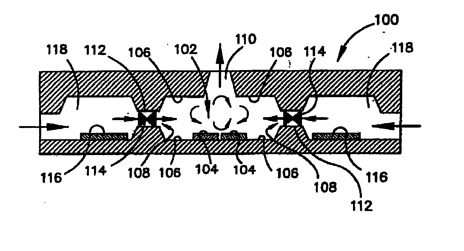
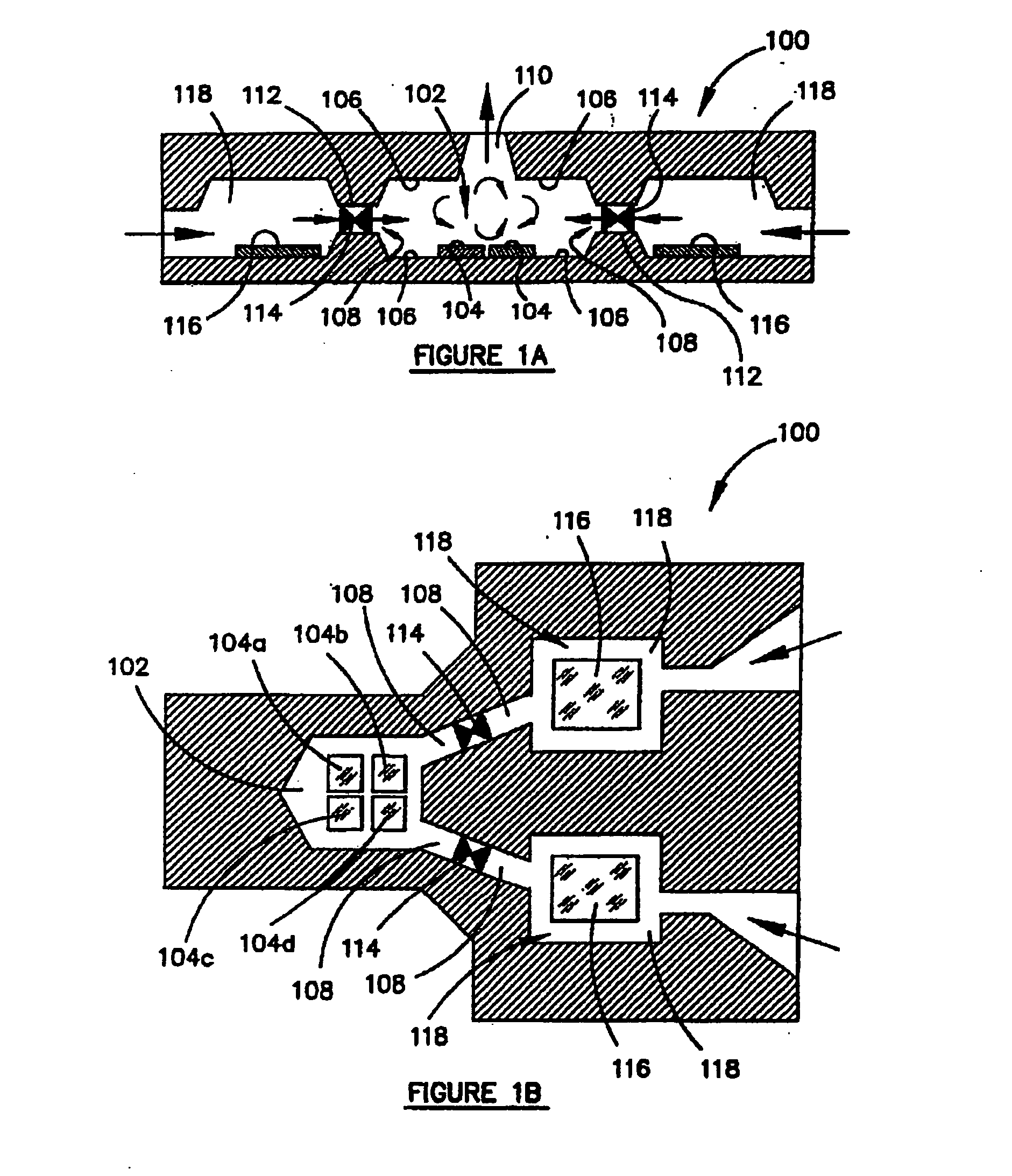
[0016]FIG. 1A is a cross-section of a body of a micro-mixer 100 in accordance with an embodiment. Incorporated into the body of the micro-mixer 100 is a micro-mixing chamber 102 having a total of four heating elements, two of which can be seen in cross section in FIG. 1A. The heating elements 104 heat liquid in the chamber 102 so as create a vapor bubble and thereby cause liquid turbulence and mixing in the mixing chamber 100. As will be explained in greater detail bel...


PUM


Abstract

A micro-mixer 100 having a body in which there is disposed a micro-mixing chamber for mixing liquid. Micro-channels 108 extend from an external surface of the body of the micro-mixer 100 to the micro-mixing chamber 102 and define passageways for supplying liquid into the micro-mixing chamber 102. The micro-mixer 100 also has an electrical circuit that includes an electrical pulse generator that is connected to two or more spaced electrical heating elements 104 located in the mixing chamber 102 that receive electrical pulses from the pulse generator. In use, electrical pulses received by the heating elements 104 cause the heating elements to heat liquid in the mixing chamber in regions locally of each of the heating elements and thereby generating a vapour bubble which will, in turn, cause turbulence and mixing of liquid within the micro-mixing chamber.

Description

FIELD OF THE INVENTION [0001] The invention described herein relates generally to micro-mixers and more particularly to a micro-mixer having a heating element for mixing liquids. BACKGROUND OF THE INVENTION [0002] Mixing liquids on a micro-scale is presently utilized in a number of bio-medical and life science applications such as in the detection and analysis of diseases, viruses and other pathological tests. Examples of liquids that are mixed on a micro-scale include blood plasma and solutions containing DNA and reproductive cells. [0003] Mixing liquids on a micro-scale has several advantages. For example, mixing-liquids on a micro-scale reduces the amount of liquid being consumed and from a technical point of view, can allow the analysis of microscopic specimens to selected conditions. Micro-mixers are also known as micro-electromechanical systems (MEMS) and are sometimes called micromechanical devices, micromachines, micro-fabricated devices or nano-structures. In some instances...

Claims


Application Information

Patent Timeline
Patent Type & Authority Applications(United States)
IPC IPC(8): B01F15/06
CPCB01F13/0079B01F13/02F16K99/0057F16K99/0001F16K99/0021B01L3/5027B01F33/3033B01F33/40
Inventor SURIADI, ARIEF BUDIMANSOW, CHORNG ING
Owner HEWLETT PACKARD DEV CO LP
Learn More