Switching system for virtual LANs

a virtual lan and switching system technology, applied in the field of network switches, can solve the problems of over-expensive solutions, failure of any given switch, and destruction of the integrity of the entire switching system,

a virtual lan and switching system technology, applied in the field of network switches, can solve the problems of over-expensive solutions, failure of any given switch, and destruction of the integrity of the entire switching system,

US20060029072A1Inactive Publication Date: 2006-02-09RAPTOR NETWORKS TECH

Image

  • Switching system for virtual LANs
  • Switching system for virtual LANs
  • Switching system for virtual LANs

Examples


Embodiment Construction

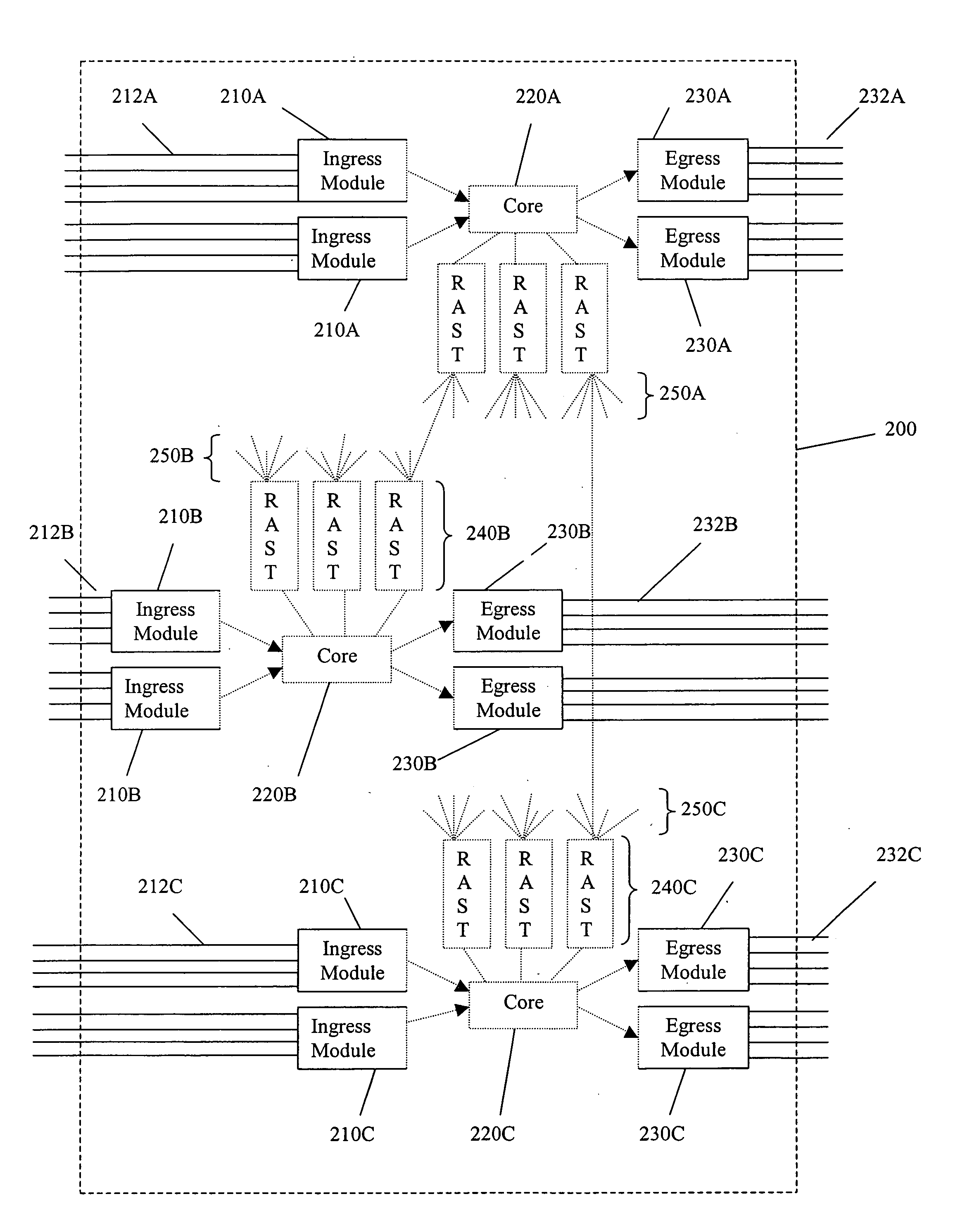
[0028] In FIG. 2 a switching system 200 generally includes ingress elements 210A-C, egress elements 230A-C, core switching elements 220A-C and connector elements 240A-C. The ingress elements encapsulate incoming packets with a routing header (see FIG. 3), and perform initial switching. The encapsulated packets then enter the core elements for further switching. The intermediate elements facilitate communication between core elements. The egress elements remove the header, and deliver the packets to a sink or final destination.

[0029] Those skilled in the art will appreciate that switching (encapsulation) header must, at a bare minimum, include at least a destination element address. In preferred embodiments the header also includes destination port ID, and where elements are clustered and optional destination cluster ID. Also optional are fields for source cluster, source element, and source port IDs. As used herein an “ID” is something that is the same as, or can be resolved into a...


PUM


Abstract

A switch encapsulates incoming information using a header, and removes the header upon egress. The header is used by both distributed ingress nodes and within a distributed core to facilitate switching. The ingress and egress elements preferably support Ethernet or other protocol providing connectionless media with a stateful connection. Preferred switches include management protocols for discovering which elements are connected, for constructing appropriate connection tables, for designating a master element, and for resolving failures and off-line conditions among the switches. Secure data protocol (SDP), port to port (PTP) protocol, and active / active protection service (AAPS) are all preferably implemented. Systems and methods contemplated herein can advantageously use Strict Ring Topology (SRT), and conf configure the topology automatically. Components of a distributed switching fabric can be geographically separated by at least one kilometer, and in some cases by over 150 kilometers.

Description

[0001] This application claims priority to provisional application number 60 / 511,145 filed Oct. 14, 2003; provisional application number 60 / 511,144 filed Oct. 14, 2003; provisional application number 60 / 511,143 filed Oct. 14, 2003; provisional application number 60 / 511,142 filed Oct. 14, 2003; provisional application number 60 / 511,141 filed Oct. 14, 2003; provisional application number 60 / 511,140 filed Oct. 14, 2003; provisional application number 60 / 511,139 filed Oct. 14, 2003; provisional application number 60 / 511,138 filed Oct. 14, 2003; provisional application number 60 / 511,021 filed Oct. 14, 2003; and provisional application number 60 / 563,262 filed Apr. 16, 2004, all of which are incorporated herein by reference in their entirety.FIELD OF THE INVENTION [0002] The field of the invention is network switches. BACKGROUND [0003] Modem computer networks typically communicate using discrete packets or frames of data according to predefined protocols. There are multiple such standards,...

Claims


Application Information

Patent Timeline
09 Feb 2006
Publication
US20060029072A1
IPC
H04L12/56; H04L12/28; G06F
CPC
H04L49/102; H04L49/552; H04L49/351; H04L49/3009
Inventors
PERERA, ANANDA; HOFFMAN, EDWIN