Lamp holder comprising lamp socket, ballast, and fastening mechanism, and lighting kit containing said lamp holder

a technology of ballast circuit and lamp socket, which is applied in the direction of lighting support devices, lighting and heating apparatuses, coupling device connections, etc., can solve the problems of increasing volume, increasing the number of mounting sites, and wasting the good ballast circuit together with the out-of-function lamp,

Inactive Publication Date: 2006-02-23
CHEN CHUN TSUN
View PDF12 Cites 24 Cited by
  • Summary
  • Abstract
  • Description
  • Claims
  • Application Information

AI Technical Summary

Problems solved by technology

It is a waste to throw away the good ballast circuit together with the out-of-function lamp.
The separation of the ballast from the lamp socket results in not only an increase in volume, but also the number of mounting sites, thereby making it difficult to incorporate the PL lamp into the lighting fixtures such as a floor lamp, ceiling lamp, wall sconce and outdoor lantern, and thus is not cost-effective and design-friendly.
Therefore, these lamp holders have the same problem as the self-ballasted compact fluorescent lamp, which is the incandescent lamp and the lamp holders are often used interchangeable in the same lighting fixture as a matter of convenience.
Further, these lamp holders have a metal base as the incandescent lamp, and thus they are not suitable for outdoor use, because water can easily migrates into the gap between the metal base and the lamp socket.

Method used


Image

  • Lamp holder comprising lamp socket, ballast, and fastening mechanism, and lighting kit containing said lamp holder
  • Lamp holder comprising lamp socket, ballast, and fastening mechanism, and lighting kit containing said lamp holder
  • Lamp holder comprising lamp socket, ballast, and fastening mechanism, and lighting kit containing said lamp holder

Examples


fifth embodiment

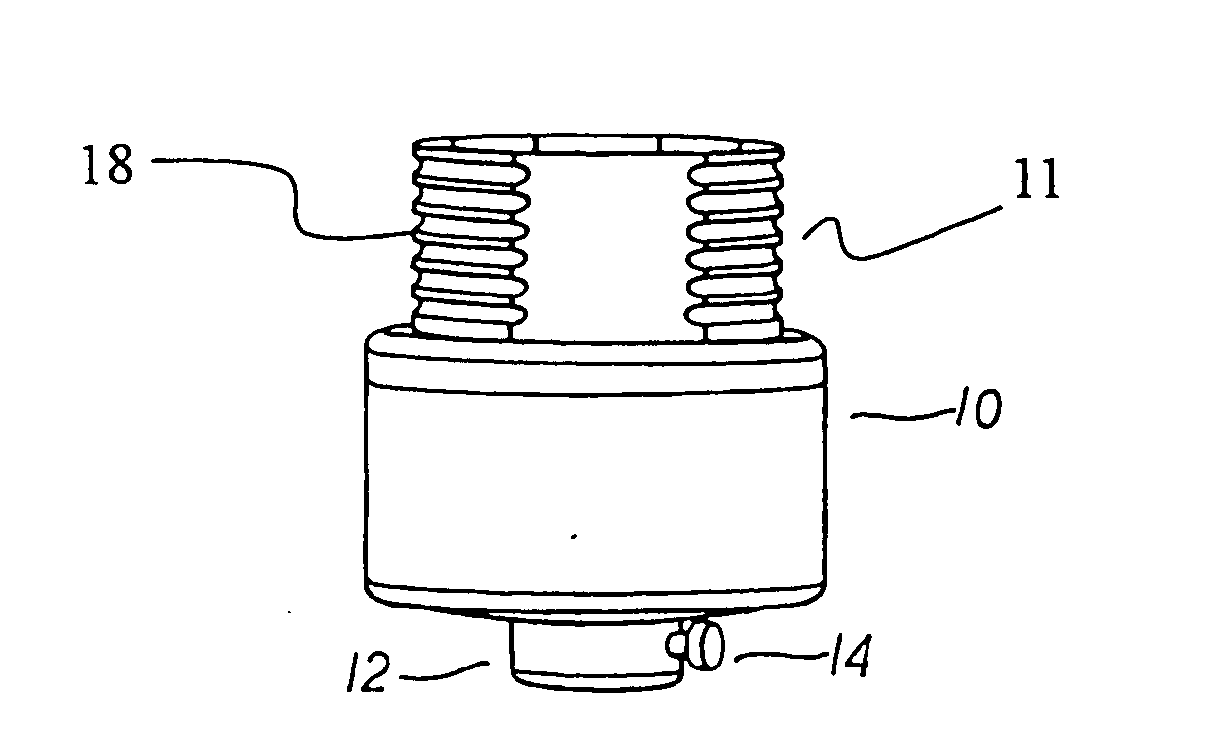
[0045] As shown in FIG. 8, a lamp holder constructed according to the present invention is similar in construction to the lamp holder shown in FIGS. 1-4, with the difference being that the former comprises a switch which is provided internally in the ballast circuit, and a knob 21 protruding from the main body 10 to control the on / off of the switch.

sixth embodiment

[0046] As shown in FIG. 9, a lamp holder constructed according to the present invention is similar in construction to the lamp holder shown in FIGS. 1-4, with the differences being that the former comprises a dome-shape main body 10 and does not have the fastening screw 14, so that the lamp holder of this embodiment is more suitable to be mounted inside a housing of a lighting fixture having a limited space for mounting the lamp socket, for examples ceiling fan lighting kits and the outdoor lantern.

[0047] As shown in FIG. 10, a lamp holder constructed according to a seventh embodiment of the present invention is similar in construction to the lamp holder shown in FIGS. 1-4, with the differences being that the former does not have the protrusion 12, the threaded hole 13 and the fastening screw 14, but contains a hole 13′ at the cylindrical surface of the main body 10, in which two bushing terminals electrically connected to the ballast circuit are provided for receiving two electrica...

ninth embodiment

[0048] As shown in FIG. 12, a lamp holder constructed according to the present invention is similar in construction to the lamp holder shown in FIG. 10, with two major differences being that the former does not have the threads 18, and the former comprises two lugs 19 extending radially from periphery of the bottom end of the main body 10. Further a through hole 19A is provided at each lug 19 for receiving a fastening screw. The lamp holder of this embodiment is in particular adapted to a vanity fixture.


PUM


Abstract

A lamp holder includes, a hollow main body; a ballast circuit disposed in said hollow main body; a socket for holding a compact fluorescent lamp on to said hollow main body; and a fastening mechanism for non-electrically fastening said hollow main body to a lighting fixture, wall, or ceiling, wherein said ballast circuit is electrically connected with electrodes of said compact fluorescent lamp when said compact fluorescent lamp is held on by said socket.

Description

FIELD OF THE INVENTION [0001] The present invention relates generally to a lighting fixture, and ore particularly to a lamp holder comprising a lamp socket, a ballast circuit, and a mechanism for fastening the lamp holder to a lighting fixture, wall or ceiling. BACKGROUND OF THE INVENTION [0002] The self-ballasted compact fluorescent lamp is widely used by virtue of its energy efficiency and is intended to replace the incandescent lamp. In light of the self-ballasted compact fluorescent lamp and the incandescent lamp being compatible in terms of lamp base, they are often used interchangeably as a matter of convenience. As a result of the interchangeable use of the self-ballasted compact fluorescent lamp and the incandescent lamp, the intended advantage of the energy efficiency of the self-ballasted compact fluorescent lamp is thus canceled out. Furthermore, the compact fluorescent lamp of the self-ballasted compact fluorescent lamp has a working life which is significantly shorter t...

Claims


Application Information

Patent Timeline
Patent Type & Authority Applications(United States)
IPC IPC(8): F21S8/00F21V19/00F21V23/02F21V23/04F21V31/00H01R33/08
CPCF21V19/0095F21V21/116F21V23/02F21V23/026F21V23/04Y02B20/19F21W2131/10H01J61/327H01J61/56H01J61/72H01R33/0809F21V31/00Y02B20/00
Inventor CHEN, CHUN TSUN
Owner CHEN CHUN TSUN
Why Eureka
Try Eureka