
Card holder for SIM socket

Inactive Publication Date: 2006-02-23
JST MFG CO LTD
View PDF13 Cites 22 Cited by
  • Summary
  • Abstract
  • Description
  • Claims
  • Application Information

AI Technical Summary

Benefits of technology

[0015] With this structure, since the contact piece of the card holder is extended more outwardly than the outer surface of the slide part, the contact piece of the card holder inserted therein reaches a state of being pressed against the inside face of the guide wall of the SIM socket. Therefore, the card holder inserted therein can be prevented from moving in the width direction (i.e., direction perpendicular to the insertion direction) . Additionally, since the contact piece of the card holder is pressed against the inside face of the guide wall of the SIM socket when the card holder is inserted, the card holder can be smoothly inserted.
[0016] Preferably, the contact piece has a bulging shape. If the contact piece is shaped like this, the contact piece can elastically move in the width direction with ease.
[0017] Preferably, a space exists between the contact piece and a main body of the card holder. This space enables the contact piece to move more elastically.
[0018] Preferably, the slide part of the card holder has a first engagement part that is engaged with a rear lock part provided on the guide wall of the SIM socket in a state in which the card holder is inserted into an inmost part. Since the first engagement part is engaged with the rear lock part of the SIM socket in a state in which the card holder holding the memory card is inserted, the card holder can be locked at a predetermined position of the connector housing so that the card holder holding the memory card does not easily move in the insertion direction.
[0019] Preferably, the side face of the card holder has a second engagement part that is engaged with a front lock part provided on the guide wall of the SIM socket in a state in which the card holder is drawn out to a hithermost part. Since the second engagement part is engaged with the front lock part of the SIM socket when the card holder holding the memory card is extracted, the card holder can be temporarily stopped at a predetermined position of the connector housing so that the card holder holding the memory card does not easily fall off.
[0020] Preferably, a slit extending in the insertion direction is formed near a front end of the card holder of the present invention. This slit enables the second engagement part to easily move in the width direction and easily go beyond the front lock part when the card holder holding the memory card is inserted.

Problems solved by technology

As a result, oxidization becomes liable to occur, and causes a contact failure.
Additionally, there is a case in which an excessive force is applied to the connection terminal if the card holder cannot be smoothly slid while it is being inserted.
Likewise, this causes a contact failure.

Method used


Image

  • Card holder for SIM socket
  • Card holder for SIM socket
  • Card holder for SIM socket

Examples


Embodiment Construction

[0031] A description will be hereinafter given of an embodiment of the present invention taking, as an example, a SIM socket attached to a circuit board in a mobile telephone.

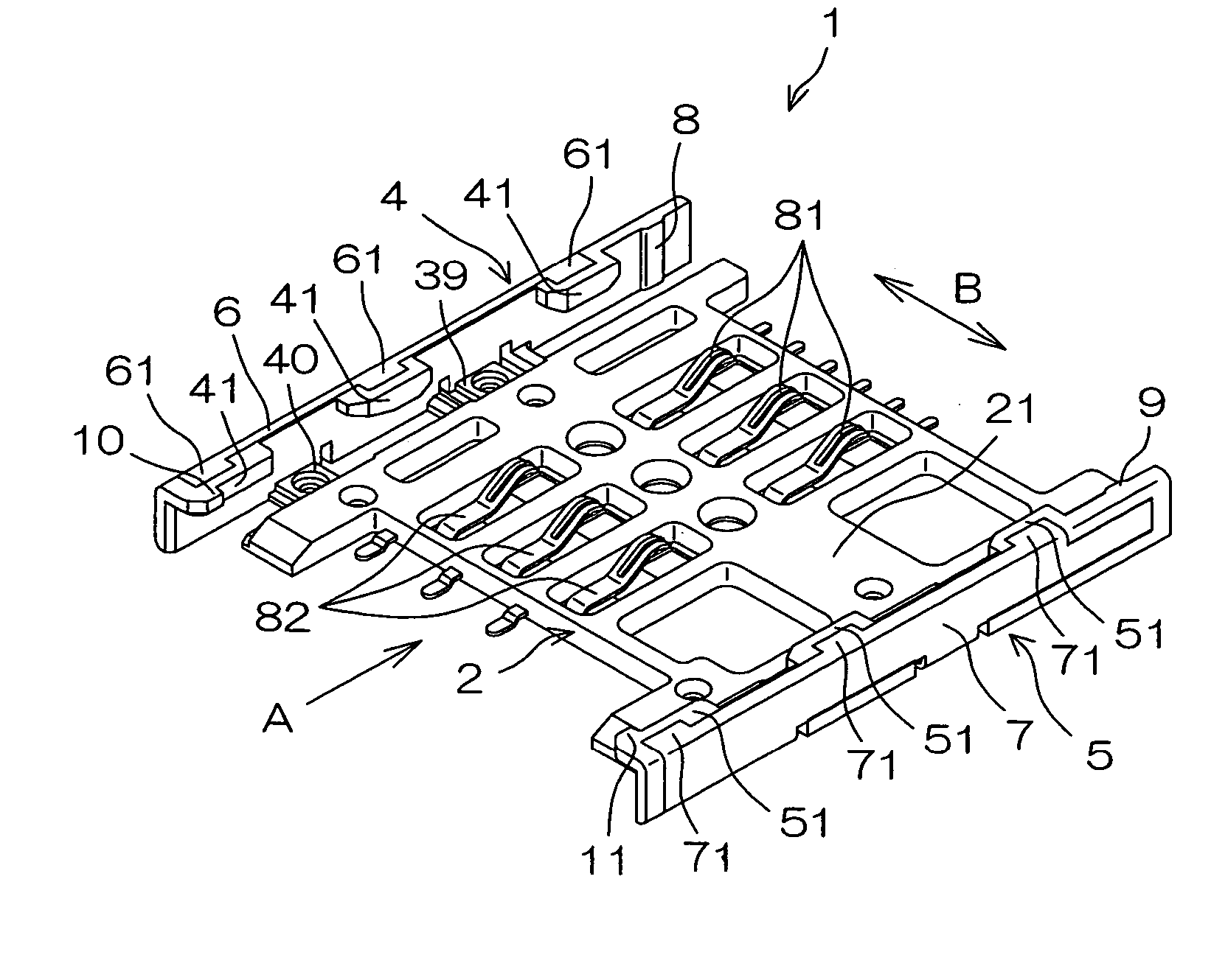
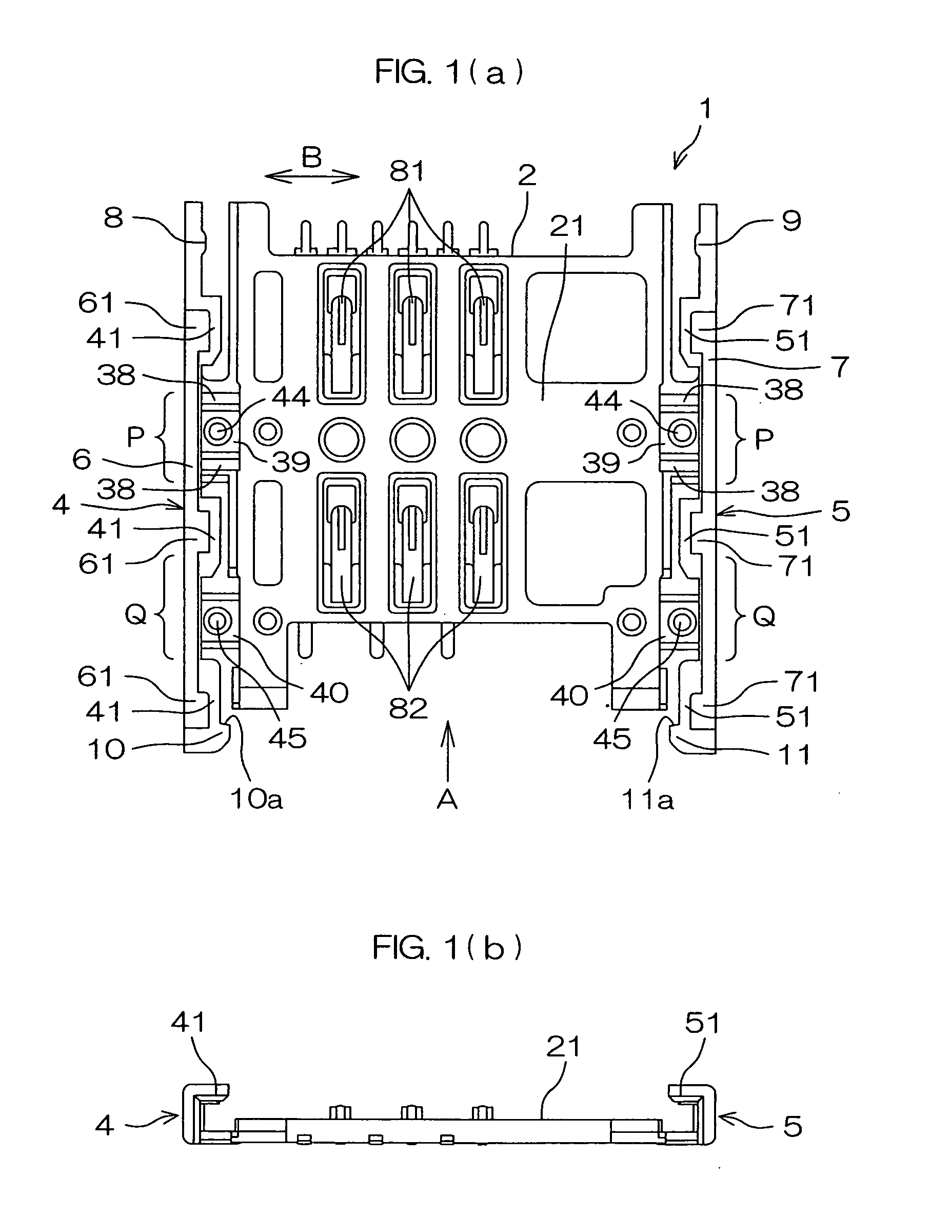
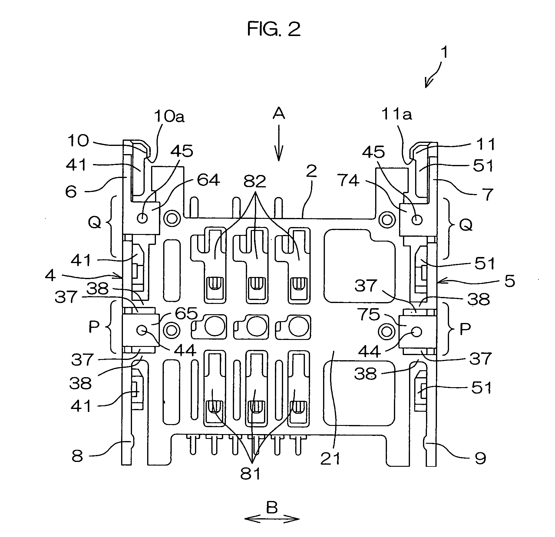
[0032]FIG. 1(a) is a plan view of a SIM socket, and FIG. 1(b) is a front view of the SIM socket. FIG. 2 is a bottom view of the SIM socket, and FIG. 3 is a perspective view of the SIM socket.

[0033] The SIM socket 1 is molded while inserting metallic connection terminals into an insulating plastic material such as polyamide resin. A part thereof made of the plastic material is a connector housing 2 that can receive a card holder 3 (see FIG. 4, described later).

[0034] The connector housing 2 is resinous and flat. This flat resin plate is designated by reference numeral 21. A direction in which a card holder 3 is inserted is designated by “A”.

[0035] Guide walls 4 and 5 used to slide-insert the card holder 3 are erected on right and left sides of the flat resin plate 21 when seen from the insertion direction “A...


PUM


Abstract

Slide parts (32,33), along which the card holder (3) is slid in, are formed on side faces of the card holder (3) along inside faces of guide walls (4,5) of a SIM socket (1). Each of the slide parts (32,33) has a contact piece (36) extended more outwardly than outer surfaces of the slide parts (32,33). The contact piece (36) of the card holder (3) reaches a state of being pressed against the inside faces of the guide walls (4,5) of the SIM socket (1). Therefore, the card holder (3) inserted therein can be prevented from moving in the width direction (B) (i.e., in the direction perpendicular to the insertion direction). Additionally, since the card holder (3) is inserted while allowing the contact piece (36) to be pressed against the inside faces of the guide walls (4,5) of the SIM socket (1), the card holder (3) can be smoothly inserted.

Description

BACKGROUND OF THE INVENTION [0001] 1. Field of the Invention [0002] This invention relates to a card holder that holds a memory card used in communication devices such as mobile telephones, and, more particularly, to a card holder that can be inserted into a SIM socket attached to a circuit board in a device body. [0003] 2. Description of Related Art [0004] A communication device (hereinafter, referred to as “mobile telephone etc.”), such as a mobile telephone or a PDA, is used in a state of registering personal information. Therefore, when the present model is changed to a new model, the personal information registered thereon is desirably required to be easily transferred from the present model to the new model. [0005] Accordingly, a structure has been employed in which personal information is stored in a memory card, in which a SIM (Subscriber Identification Module) socket is attached to an internal substrate of a mobile telephone etc., and in which the memory card is detachably ...

Claims


Application Information

Patent Timeline
IPC IPC(8): H01R24/00
CPCH01R13/24H01R12/714H04B1/3816H01R2201/16G06K7/0021
Inventor UCHIDA, SHINJIIMAIZUMI, TETSUICHIRO
Owner JST MFG CO LTD
Learn More