
Lockable electric connector

Inactive Publication Date: 2005-04-07
JST MFG CO LTD
View PDF0 Cites 6 Cited by
  • Summary
  • Abstract
  • Description
  • Claims
  • Application Information

AI Technical Summary

Benefits of technology

[0016] It is an object of the present invention to provide a lockable electric connector into which a ribbed socket can smoothly be inserted.
[0017] It is another object of the present invention to provide a lockable electric connector capable of preventing the contact from being damaged when connected to a socket.

Problems solved by technology

However, machines of various types are different from one another in the positions of and the distances between function modules.
However, the ribs formed on outer faces (in particular on the lateral faces) of a socket, come in contact with the engaging projection of the locking claw of the relay connector, thus disadvantageously preventing a smooth insertion of the socket.
This involves the likelihood that the post pins exposed in the engaging concave are disadvantageously deformed.
Further, even though it is tried to insert a socket in a wrong posture, the socket tip reaches the engaging concave of the relay connector.
Such problems are also encountered with a base connector as another example of the lockable electric connector.

Method used


Image

  • Lockable electric connector
  • Lockable electric connector
  • Lockable electric connector

Examples


first embodiment

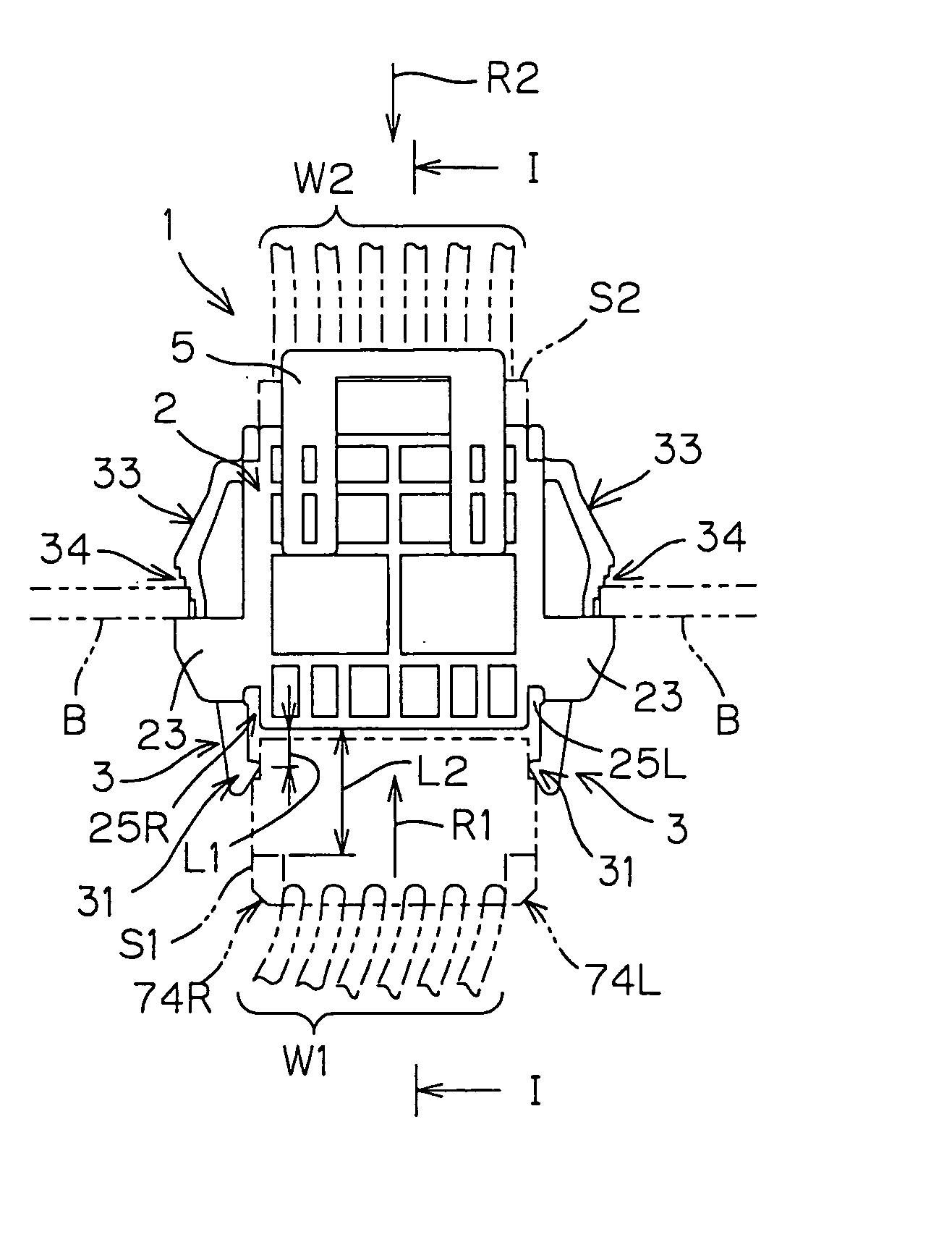
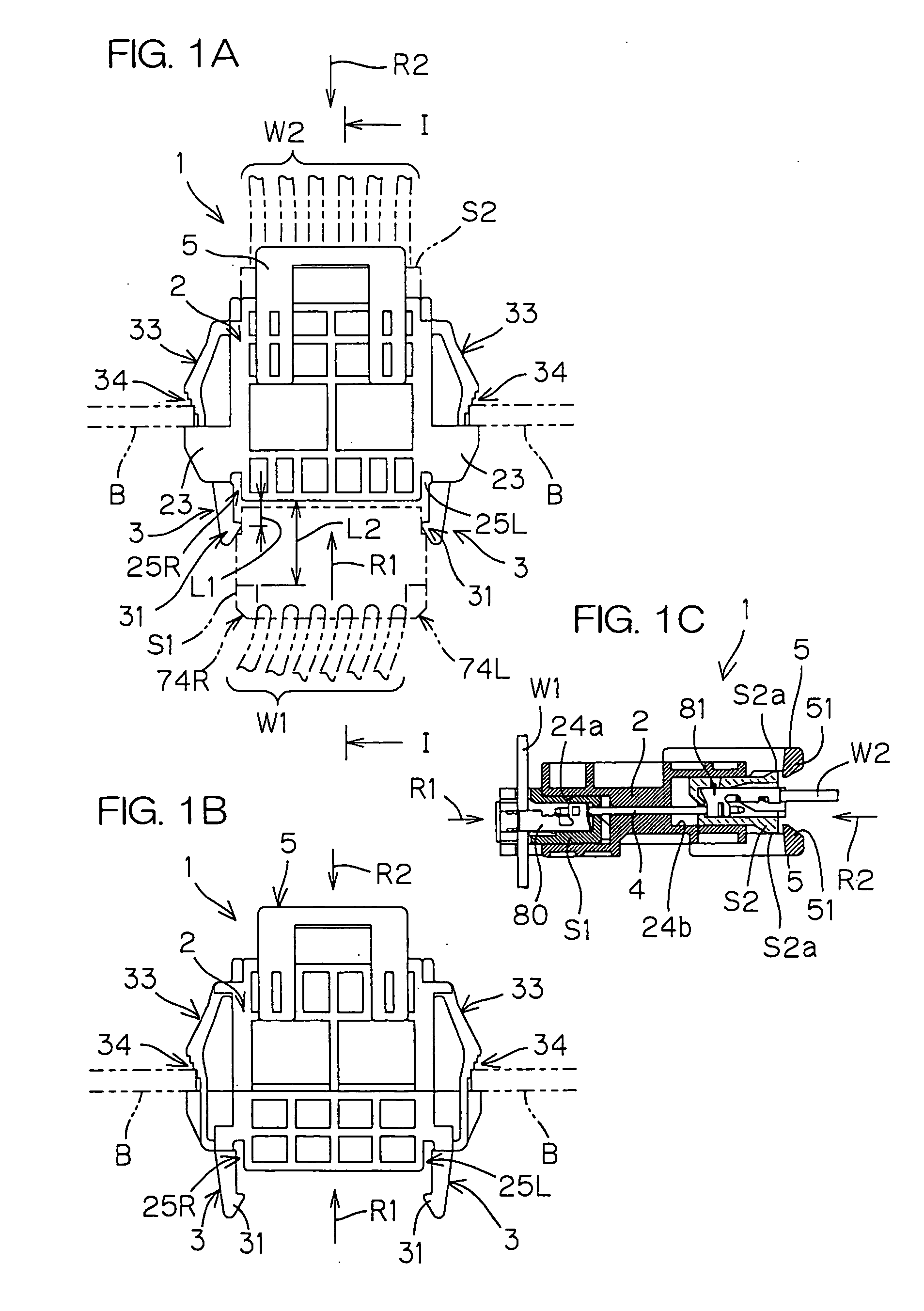
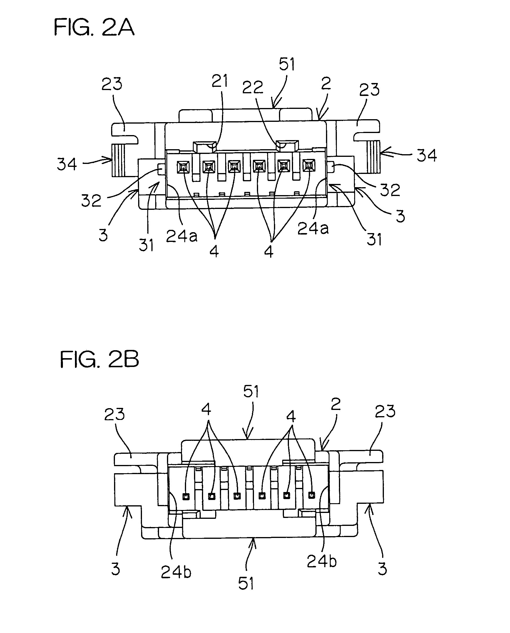
[0039]FIG. 1A is a plan view of a relay connector 1 according to the present invention, and FIG. 1B is a bottom view of this relay connector 1. FIG. 1C is a section view taken along the line I-I in FIG. 1A. FIG. 2A is a front view of the relay connector 1 viewed from a socket S1 side, and FIG. 2B is a back view of the relay connector 1 viewed from a socket S2 side.

[0040] The relay connector 1 is a connector for relaying and electrically connecting a pair of sockets S1, S2 mounted thereon. For example, one of the sockets S1, S2 is fixed to the ends of electric wires W1 forming a wire harness, and the other socket is fixed to ends of electric wires W2 forming extension wirings for connecting a base connector on a printed circuit board and the wire harness to each other. When the sockets S1, S2 are mounted on the relay connector 1, contacts 80, 81 of the sockets S1, S2 come in contact with both ends of post pins 4 of the relay connector 1 as shown in FIG. 1C. Thus, the electric wires W...

second embodiment

[0056]FIG. 5A is a plan view of a relay connector 10 according to the present invention, FIG. 5B is a bottom view of the relay connector 10, and FIG. 5C is a section view taken along the line V-V in FIG. 5A. In FIGS. 5A, 5B, 5C, like parts are designated by like reference numerals used in FIGS. 1A, 1B, 1C.

[0057] The relay connector 10 is provided in a housing 2 thereof with fitting concaves 24c, 24d in association with both ends of post pins 4. A pair of locking claws 3 project from both lateral sides of one fitting concave 24c toward the upstream side in the insertion direction R1, and a pair of locking claws 3A project from both lateral sides of the other fitting concave 24d toward the upstream side in the insertion direction R2. The locking claws 3, 3A have substantially the same arrangement.

[0058] More specifically, the locking claws 3, 3A are provided at the tips thereof with engaging projections 31 having guide grooves 32. The guide grooves 32 are formed as corresponding to e...


PUM


Abstract

A lockable electric connector to be fitted and electrically connected to a socket provided on an outer face thereof with a rib extending in the insertion direction. The electric connector is provided with: a contact; a housing which has a fitting concave for receiving the socket, and which holds the contact such that a portion of the contact is exposed in the fitting concave; and a locking claw formed as projecting from the housing toward the upstream side in the socket insertion direction for holding the fitting state of the socket to the lockable electric connector. The locking claw has an engaging projection to be locked and engaged with an engaging portion of the socket, the engaging projection being formed at a position upstream with respect to the fitting concave in the socket insertion direction. The engaging projection has a guide groove for guiding the rib of the socket, the guide groove extending in the socket insertion direction.

Description

BACKGROUND OF THE INVENTION [0001] 1. Field of the Invention [0002] The present invention relates to an electric connector such as a relay connector for relaying sockets or a base connector disposed on a printed circuit board, the electric connector having locking claws for holding the fitting state of the socket(s) to the connector. [0003] 2. Description of Related Art [0004] An electric connector fixed onto a printed circuit board is called a base connector, and a connector connected to the tips of wires or cables is called a socket. Further, a connector for relaying the connection between sockets, is called a relay connector. [0005] For example, a mechanical apparatus having a plurality of functional units such as a vending machine, is provided with a plurality of units such as an illumination unit for illuminating the commercial products, a sensor unit for detecting coins and bills, a discharge unit for discharging a commercial product to the outlet slot, and the like. Since the...

Claims


Application Information

Patent Timeline
IPC IPC(8): H01R13/639H01R13/627H01R13/74
CPCH01R13/6273H01R13/743H01R13/741H01R13/639
Inventor KUBO, TSUKASAHORII, TOSHIAKI
Owner JST MFG CO LTD
Learn More