
Direction changing device, medical assembly having the same, and method

Active Publication Date: 2013-08-15
TERUMO KK
View PDF5 Cites 5 Cited by
  • Summary
  • Abstract
  • Description
  • Claims
  • Application Information

AI Technical Summary

Benefits of technology

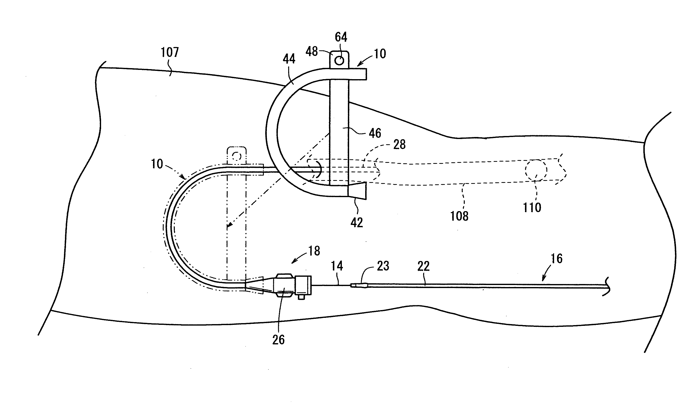
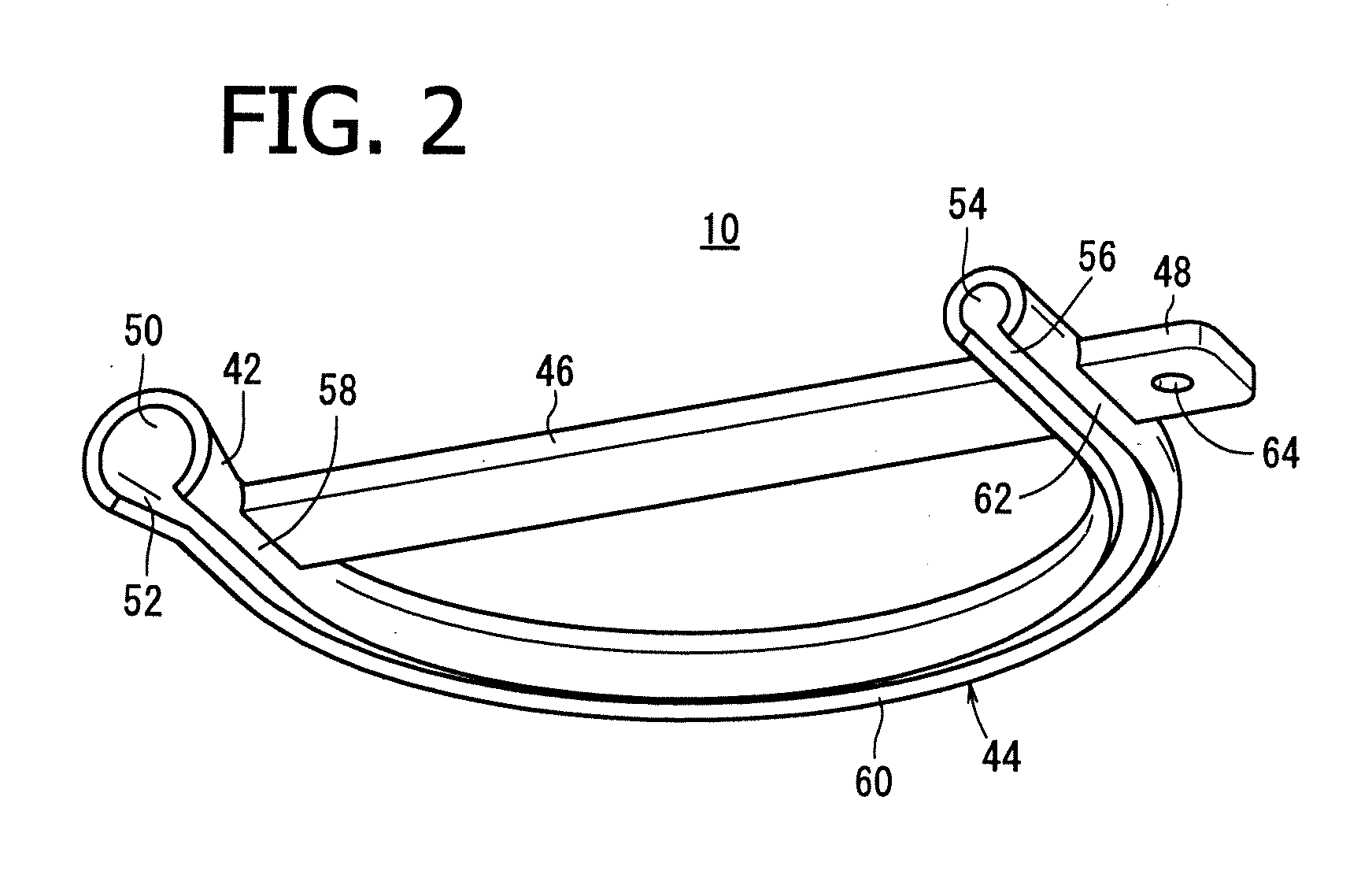
The direction changing device described in this patent allows for easy and efficient insertion of a catheter into a sheath introducer. By curving the first mounting section and the second mounting section in opposite directions, the direction of insertion of the sheath introducer and the direction of insertion of the catheter can be easily made different, ensuring that the catheter can be easily operated by the operator's dominant hand. This results in a more efficient and targeted insertion of the catheter into the living body.

Problems solved by technology

Therefore, for example in the case where the direction of insertion of the sheath tube into the living body is rightward with respect to the operator who stands facing the patient, it is difficult for the operator to manipulate the catheter with their right hand to insert the catheter into the sheath introducer.
On the other hand, for example where the direction of insertion of the sheath tube into the living body is leftward with respect to the operator who stands facing the patient, it is difficult for the operator to operate the catheter with their left hand to insert the catheter into the sheath introducer.
This may make it very difficult for the operator to efficiently insert the catheter into the living body.

Method used


Image

  • Direction changing device, medical assembly having the same, and method
  • Direction changing device, medical assembly having the same, and method
  • Direction changing device, medical assembly having the same, and method

Examples


first embodiment

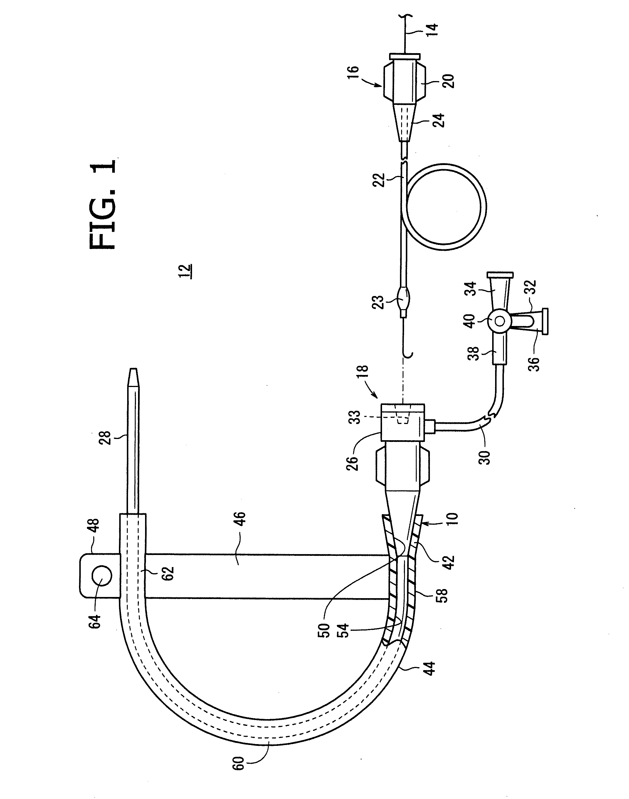
[0084]As shown in FIG. 1, a medical assembly 12 has a guidewire 14, a catheter 16, a sheath introducer 18, and a direction changing device 10. Incidentally, the sheath introducer 18 includes not only a sheath but also a long sheath and a guiding sheath.

[0085]The guidewire 14 is a member which is inserted in a lumen of the catheter 16 and by which the catheter 16 is guided in an organ of a living body such as a blood vessel to a predetermined target site therein. A distal portion of the guidewire 14 has been set, for example, into a roughly J-shaped form. Examples of the material forming the guidewire 14 include a polyurethane resin and stainless steel. The shape of the distal portion of the guidewire 14 is not limited to the above-mentioned shape but may be others such as a straight shape, an angular shape or the like.

[0086]The catheter 16 is configured to be percutaneously inserted into an organ of a living body, such as a blood vessel, for diagnosis or treatment of a part thereof ...

second embodiment

[0148]Now, a medical assembly 12A according to a second embodiment of the present invention will be described below, referring to FIGS. 16 to 26C. In the medical assembly 12A according to this embodiment, the same components as those of the above-described medical apparatus assembly 12 are denoted by the same reference symbols as used above, and detailed descriptions of them will be omitted.

[0149]As shown in FIG. 16, a sheath hub 26 of a sheath introducer 18 of the medical assembly 12A is a hollow member formed from a resin or the like. The sheath hub 26 includes a hub rear end section 25 having a hollow cylindrical shape, a hub intermediate section 27 which is a hollow cylindrical body smaller than the hub rear end section 25 in its outside diameter, a pair of projection pieces 29 projecting from an outer circumferential surface of the hub intermediate section 27, and a hub distal end section 31 which is provided at the distal end of the hub intermediate section 27 and tapers down ...

first modification

of Second Embodiment

[0186]A direction changing device 200a according to a first modification of this embodiment will be described below, referring to FIGS. 24A and 24B. In the direction changing device 200a according to this modification, the same components as those of the above-described direction changing device 200 are denoted by the same reference symbols as used above, and detailed descriptions of them will be omitted. The same applies also to a direction changing device 200c according to a third modification which will be described later.

[0187]As shown in FIGS. 24A and 24B, the direction changing device 200a according to this modification differs from the above-described direction changing device 200 in the configuration of an interconnecting section 220. Specifically, the interconnecting section 220 has a configuration in which one end portion of a direction changing section 202 is not integrally formed therewith; instead, there is formed a joint section 222 to which the one...


PUM


Abstract

In one form, a direction changing device is provided including: a first mounting section; and a second mounting section, wherein an axial direction of the first mounting section and an axial direction of the second mounting section intersect each other or are parallel to each other in plan view, and in a condition where a catheter or a sheath introducer in which the catheter is inserted is mounted to the first mounting section and the second mounting section, the catheter or the sheath introducer adopts a curved shape such that a catheter or sheath introducer portion mounted to the first mounting section extends proximally to distally in one direction and a catheter or sheath introducer portion mounted to the second mounting section extends proximally to distally in another direction with the directions being different from each other.

Description

CROSS-REFERENCE TO RELATED APPLICATIONS[0001]This application claims priority of Japanese Patent Application JP 2012-27185 filed on Feb. 10, 2012, Japanese Patent Application JP 2012-27182 filed on Feb. 10, 2012, and Japanese Patent Application JP 2012-208506 filed on Sep. 21, 2012, which are hereby incorporated herein by reference in their entirety.FIELD OF THE INVENTION[0002]The present invention relates to a direction changing device to be mounted to a catheter or a sheath introducer through which the catheter is passed, a medical assembly having the direction changing device, and method of using such a medical assembly.BACKGROUND OF THE INVENTION[0003]Conventionally, it has been a common practice to insert a catheter into a organ of a living body such as a blood vessel to deliver the catheter's distal portion to a lesion (for example, a stenosed part), and perform diagnosis or treatment on the lesion.[0004]Specifically, as a method of percutaneously inserting a catheter into a b...

Claims


Application Information

Patent Timeline
IPC IPC(8): A61M25/01
CPCA61M25/01A61M2025/024A61M25/02A61M25/0133
Inventor MOURI, TAKAYUKIYAGI, HIROSHI
Owner TERUMO KK
Learn More