Ultrasound handpiece

a handpiece and ultrasonic technology, applied in the field of ultrasonic devices, can solve the problems of difficult to achieve simultaneous longitudinal and torsional motion, and the resonance of the handpiece using two pairs of crystals is difficult to achiev

Active Publication Date: 2006-02-23
ALCON INC
View PDF99 Cites 133 Cited by
  • Summary
  • Abstract
  • Description
  • Claims
  • Application Information

AI Technical Summary

Problems solved by technology

These prior attempts have used electric motors to provide the rotation of the tip which require O-ring or other seals that can fail in addition to the added complexity and possible failure of the motors.
In actual practice, making a handpiece using two pairs of crystals resonate in both longitudinal and torsional directions is difficult to achieve.
Again, in practice, the resonate frequency of the piezoelectric crystals and the tip or horn did not coincide, so simultaneous longitudinal and torsional motion was difficult to achieve.

Method used


Image

  • Ultrasound handpiece
  • Ultrasound handpiece
  • Ultrasound handpiece

Examples


Embodiment Construction

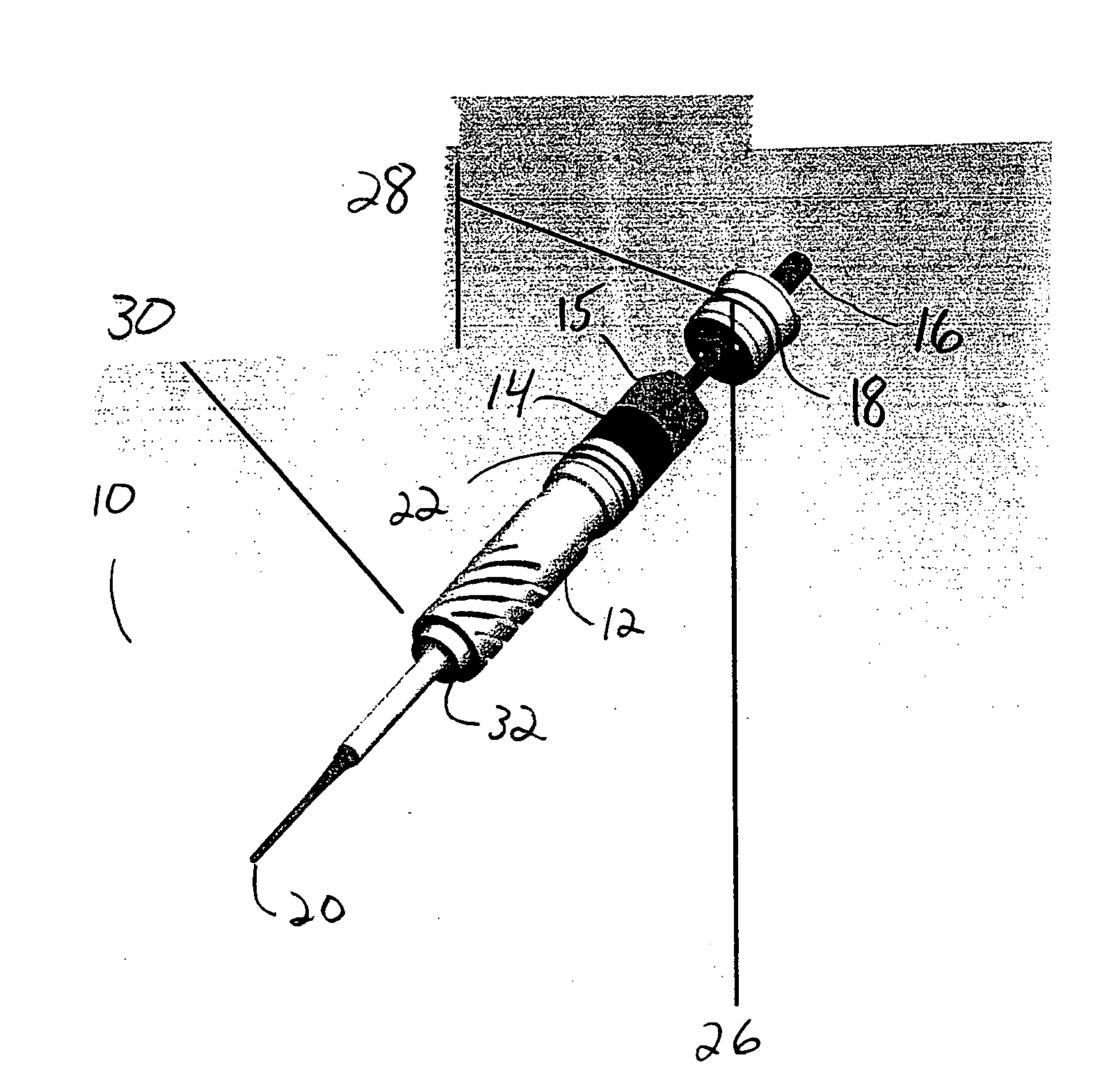
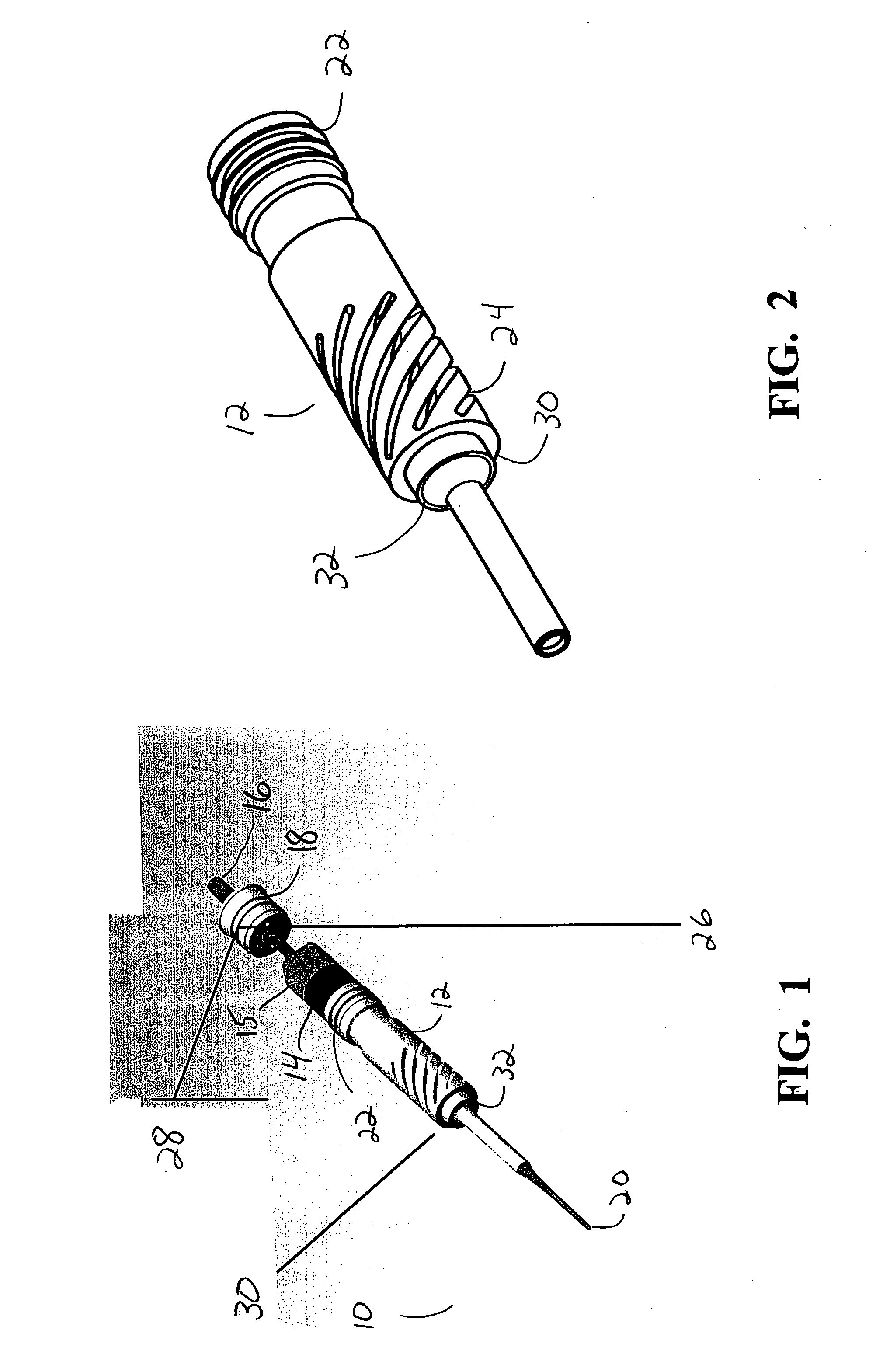
[0016] As best seen in FIG. 1 handpiece 10 of the present invention generally comprises ultrasonic horn 12, typically made from a titanium alloy. Horn 12 has a plurality of helical slits, which will be discussed below. A plurality (typically 1 or 2 pairs) of ring-shaped piezoelectric elements 14 are held by compression nut 15 against horn 12. Aspiration shaft 16 extends down the length of handpiece 10 through horn 12, piezoelectric elements 14, nut 15 and through plug 18 at the distal end of handpiece 10. Aspiration tube 16 allows material to be aspirated through hollow tip 20, which is attached to horn 12, and through and out handpiece 10. Plug 18 seals outer shell 11 of handpiece 10 fluid tight, allowing handpiece 10 to be autoclaved without adversely affecting piezoelectric elements 14. Addition grooves 22 for sealing O-ring gaskets (not shown) are provided on horn 12.

[0017] As best seen in FIG. 2, horn 12 contains a plurality of spiral slits 24. Preferably, the width of slits 2...


PUM


Abstract

A handpiece having at least one set of piezoelectric elements polarized to produce longitudinal motion when excited at the relevant resonant frequency. The piezoelectric crystals are connected to an ultrasonic horn to which a cutting tip is attached. The horn and / or the cutting tip contains a plurality of diagonal slits or grooves. The slits or grooves produce optimized torsional movement in the cutting tip when the piezoelectric crystals are excited at a second resonant frequency.

Description

[0001] This application is a continuation-in-part application of U.S. patent application Ser. No. 10 / 916,675, filed Aug. 12, 2004, currently co-pending.BACKGROUND OF THE INVENTION [0002] This invention relates to ultrasonic devices and more particularly to devices for tuning and controlling an ophthalmic phacoemulsification handpiece. [0003] A typical ultrasonic surgical device suitable for ophthalmic procedures consists of an ultrasonically driven handpiece, an attached hollow cutting tip, an irrigating sleeve and an electronic control console. The handpiece assembly is attached to the control console by an electric cable and flexible tubings. Through the electric cable, the console varies the power level transmitted by the handpiece to the attached cutting tip and the flexible tubings supply irrigation fluid to and draw aspiration fluid from the eye through the handpiece assembly. [0004] The operative part of the handpiece is a centrally located, hollow resonating bar or horn dire...

Claims


Application Information

Patent Timeline
Patent Type & Authority Applications(United States)
IPC IPC(8): A61B17/20
CPCA61B17/320068A61B2017/320096A61F9/00745A61B2017/22015A61B2017/32007A61B2017/320089A61B2017/320098
Inventor BOUKHNY, MIKHAILCHON, JAMES Y.SALEHI, AHMAD
Owner ALCON INC
Why Eureka
Try Eureka