Screed heating arrangement

a heating arrangement and screed technology, applied in the direction of roads, roads, roads, etc., can solve the problems of excessive drag, buildup of paving material, and poor working environment for paving workers

Inactive Publication Date: 2006-03-02
NELSON JAMES J
View PDF26 Cites 57 Cited by
  • Summary
  • Abstract
  • Description
  • Claims
  • Application Information

AI Technical Summary

Problems solved by technology

If the screed is not adequately heated, the bituminous mixture contacts the bottom of the screed and begins to harden, resulting in buildup of paving material and excessive drag.
Combustion of fossil fuels generates smoke that represents a source of environmental pollution, and also poses a poor working environment for the paving workers.
Additionally, because the flames or exhaust gases of the burners actually contact the screed surface, warping may result.
Additionally, the design requires loose components placed on top of one another to maintain full contact of the heating pad with the screed.

Method used


Image

  • Screed heating arrangement
  • Screed heating arrangement
  • Screed heating arrangement

Examples


Embodiment Construction

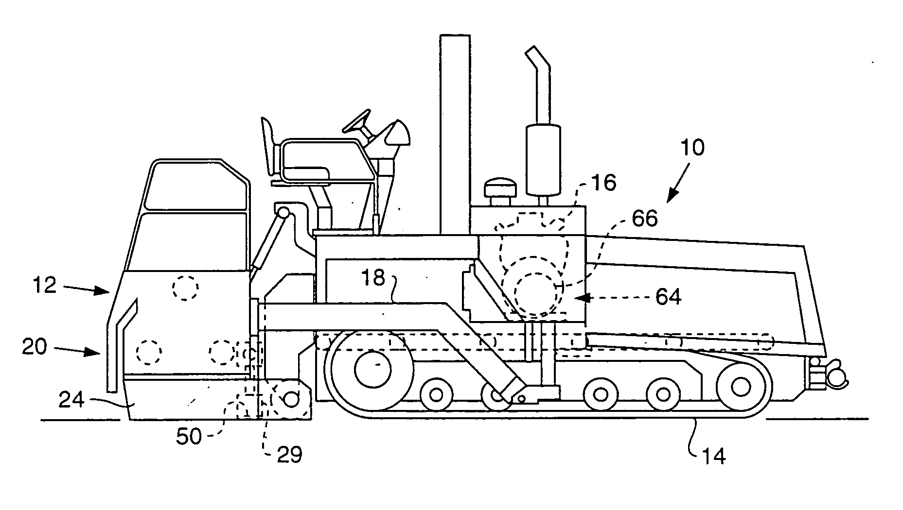
[0014] Referring to the drawings, specifically FIG. 1, an asphalt paving machine 10 is shown with a screed assembly 12 attached to the back thereof. The asphalt paving machine 10 is supported by a propelling arrangement 14 that is driven by an engine 16 in a conventional manner.

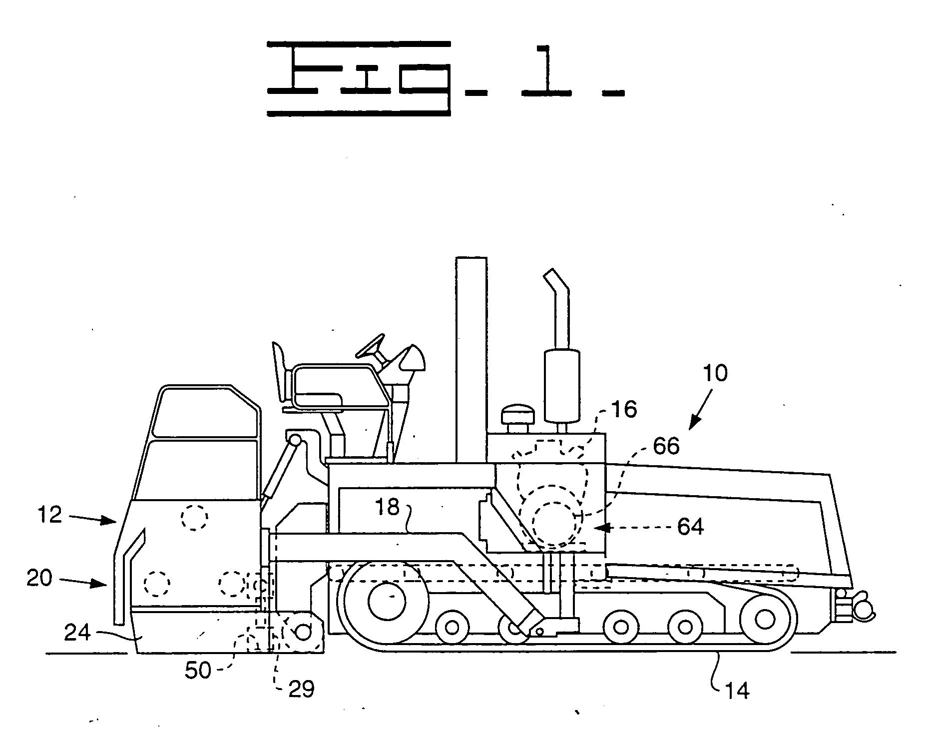
[0015] The screed assembly 12 is pivotally connected behind the asphalt paving machine 10 by tow arms 18. The screed assembly 12 may be any of a number of configurations such as a fixed width screed or a multiple section screed that includes extensions. As shown in FIG. 2, the screed assembly 12 is provided with a main screed section 20 with a left and a right screed section 22, 24. The left and right screed sections 22, 24 are hingably connected to one another along a longitudinal centerline 26 so that various operations, such as crowning, can be performed. A screed extension 28 is also provided behind and adjacent to both the left and right screed sections 22, 24. It should also be understood that screed e...


PUM


Abstract

A screed heating arrangement is provided for a screed assembly that is towed behind a paving machine. The screed heating arrangement includes at least one electric heater bonded to an upper surface of a screed plate.

Description

TECHNICAL FIELD [0001] The present invention relates to asphalt paving machines, and more particularly to an electrically heated screed arrangement. BACKGROUND [0002] The laying of asphalt paving material on road surfaces entails spreading paving material consisting of an aggregate filled bituminous mixture on a prepared roadbed. The paving material is spread while hot and is then compacted so that upon cooling a hardened pavement surface is formed. Conventional paving machines utilize a heavy assembly termed a “screed” that is drawn behind the paving machine. The screed includes a replaceable screed plate that is constructed of a suitable steel, to spread a smooth even layer of paving material on the prepared roadbed. The weight of the screed assembly aids to compress the paving material and perform initial compaction of the paving material layer. Screed assemblies can include vibratory mechanisms placed directly on the screed plate or separate vibratory tamper bars connected in ta...

Claims


Application Information

Patent Timeline
Patent Type & Authority Applications(United States)
IPC IPC(8): E01C23/14E01C19/40
CPCE01C2301/10E01C19/407E01C19/4833
Inventor NELSON, JAMES J.
Owner NELSON JAMES J
Why Eureka
Try Eureka