Paving screed

a technology of paving and screeds, applied in the field of paving screeds, can solve the problems of undue local load between the base guiding structure, the base screed, and the adjustment of the elevation of the extension screed when needed during the working process, and achieve the effects of stable support of the extension screed, high rigidity, and large guiding suppor

Active Publication Date: 2012-07-17
JOSEPH VOEGELE AG
View PDF20 Cites 31 Cited by
  • Summary
  • Abstract
  • Description
  • Claims
  • Application Information

AI Technical Summary

Benefits of technology

[0014]Expediently, the guiding sub-structure comprises a sub-structure frame having two first guiding elements which are slidably guided in the guiding tubes of the base guiding structure, and having two second guiding elements which are parallel to the first guiding elements but are offset in relation to the first guiding elements. The two guiding element pairs in the sub-structure frame result in high rigidity and large guiding support length of the guiding sub-structure despite small dimensions of the guiding sub-structure.
[0015]Expediently, the extension guiding structure comprises a frame having two spaced apart vertical plates extending perpendicular to the slide direction, and having two parallel guiding tubes fixed between and to the vertical plates. The two guiding tubes are slidably guided on the two second guiding elements of the sub-structure frame of the guiding sub-structure. The threefold combination of the base guiding structure, of the guiding sub-structure and of the extension guiding structure forms three components which can be telescoped over distinct first and second strokes in relation to each other. The sum of the first and second sliding strokes allow to reach a maximum working width substantially corresponding to the twofold width of the base screed. Even with the extension screed fully extended favourably long guiding support lengths will be maintained between respective two of the three components. The vertical plates of the extension guiding structure, furthermore, fulfil a multiple function as they stiffen the extension screed structure and assist for the vertical guidance and the adjustment of the elevation of the sole plate frame structure.
[0016]In an expedient embodiment the respective guiding support length of the guiding sub-structure in the base guiding structure and of the extension screed structure in the guiding sub-structure amount to about one third of the sum of the first and second sliding strokes. This results in a very stable support of the extension screed against forces resulting from the working process even when the extension screed is fully extended.
[0017]With a view to high rigidity and minimal mounting space the guiding tubes of the base guiding structure and the first one of the second guiding elements of the guiding sub-structure are situated substantially in a common horizontal plane. At the other side, the guiding tubes of the extension guiding structures and the two second guiding elements of the guiding sub-structure are situated substantially vertically above each other. This results in a favourable and statically determined and spatial rigidity.
[0018]Expediently, the elevation adjustment assemblies are fixed at one end either at least one guiding tube of the extension guiding structure or at the extension guiding structure itself, and at the other end at the sole plate frame structure. This results in favourable short elevation adjustment assemblies. The vertical guidances are provided between the sole plate frame structure and the vertical plates of the extension guiding structure and may be favourably long.
[0019]Expediently, the vertical guidances comprise long-slot guidances penetrated by several guiding bolts, e.g. in vertical beams of the vertical plates, in order to stably guide and support the sole plate frame structure. These long-slot guidances may be covered, preferably, by covering sheet metal fixed at the guiding bolts, such that lubricant reservoirs are kept in encapsulated and such that paving material is not allowed to intrude there. The vertical guidances, furthermore, keep away any lateral forces from the elevation adjustment assemblies, e.g. forces resulting from the working process, such that the elevation adjustment assemblies operate smoothly without jamming.

Problems solved by technology

However, that actuator has to support all weight forces of the extension screed as well as all working forces resulting from the drag resistance of the paving material at the extension screed.
In particular when the extension screed is fully extended such forces may become relatively high, which means that adjustments of the elevation of the extension screed when needed during the working process may be hindered.
The double function (adjustment of the elevation and pivoting the extension screed relative to the base screed) of the vertical actuator of a pair of vertical actuators, furthermore, result in undue high local loads between the base guiding structure, the base screed and the actuator or the actuators.

Method used


Image

  • Paving screed
  • Paving screed
  • Paving screed

Examples


Embodiment Construction

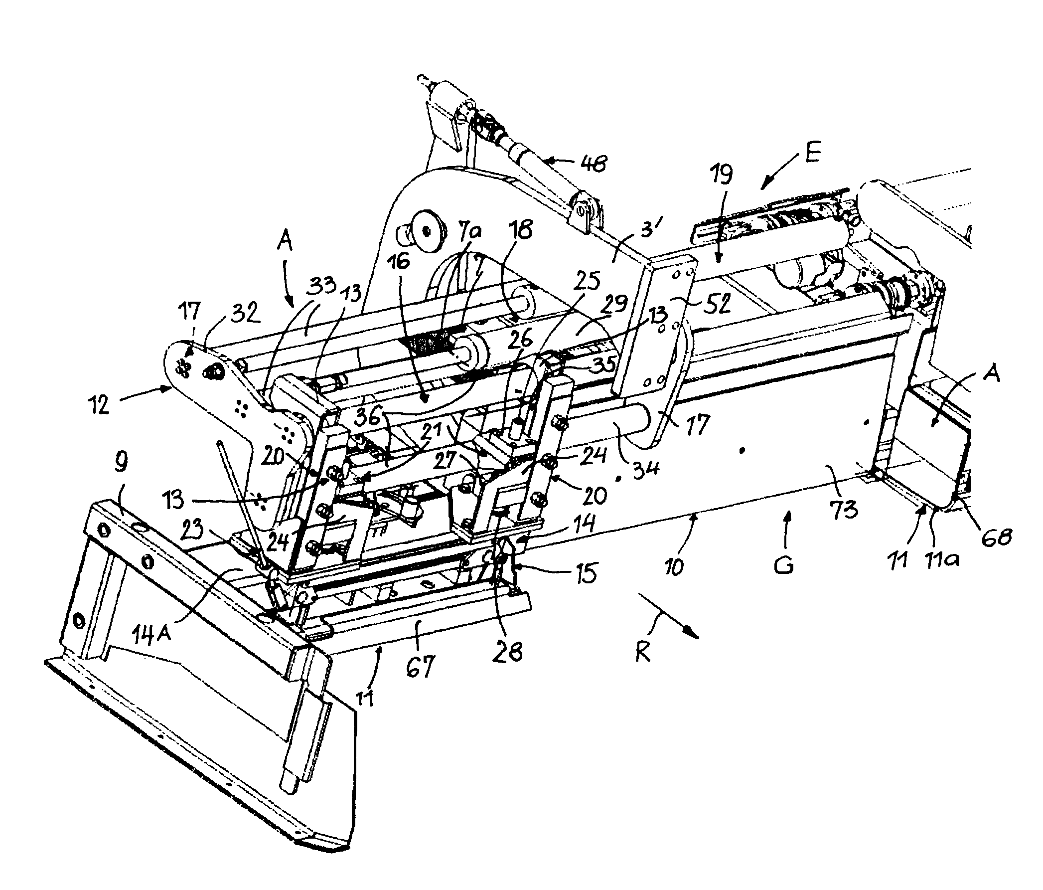
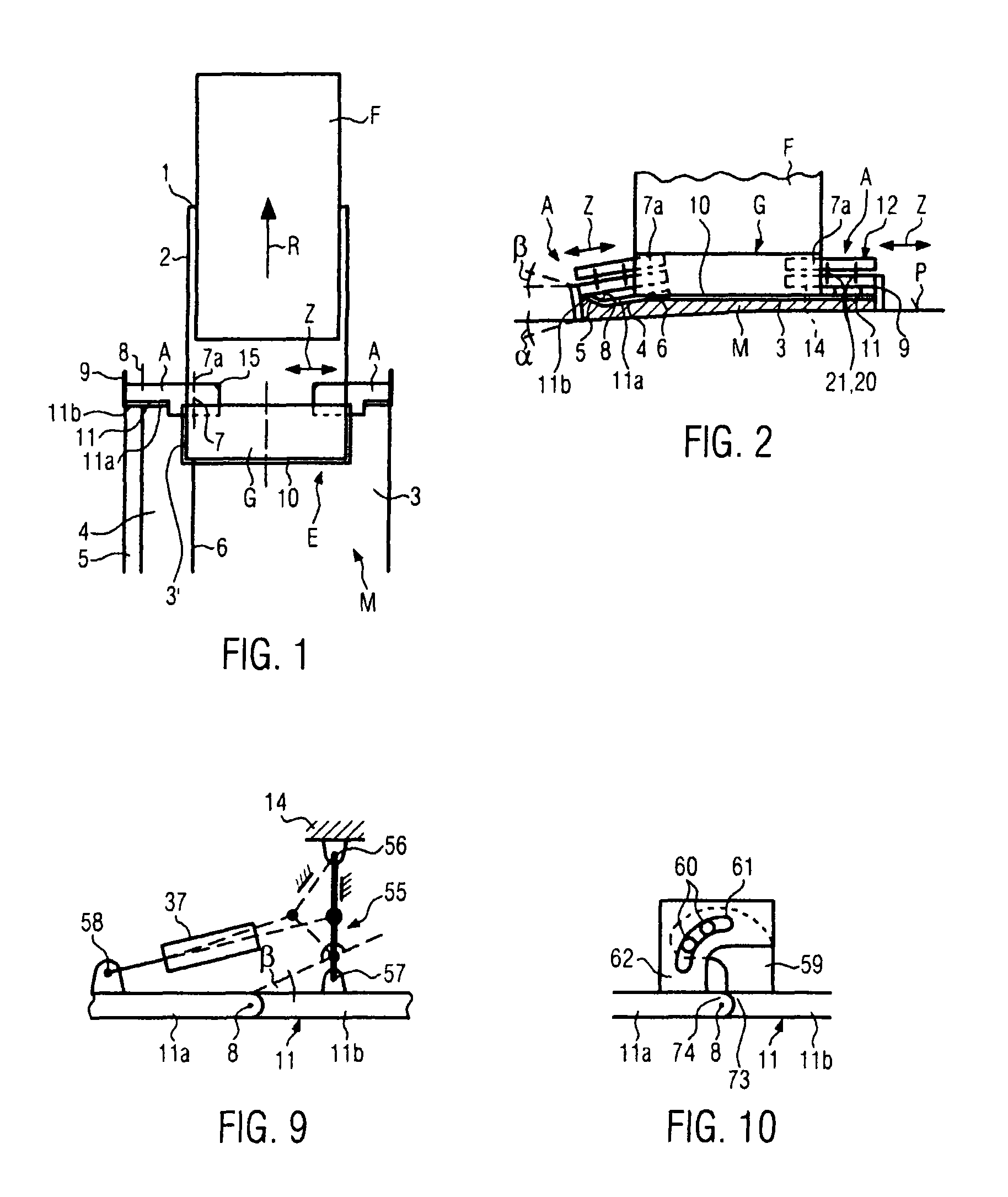
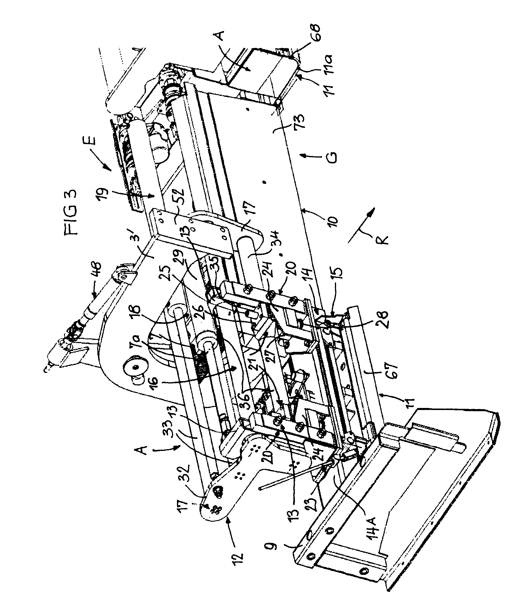
[0052]FIGS. 1 and 2 illustrate in schematic top view and schematic rear views a road paver F when constructing a roadbed M on a planum P. The road paver F is towing (working travelling direction R) a paving screed E with tow bars 2, linked to towing points 1 at the road paver F and are fixedly mounted to connection beams 3′ of the paving screed E. The towing points 1 may be adjusted e.g. vertically, at both sides of the road paver for the same amounts or for different amounts. The height positions of the towing points 1 influence the layer thickness of the roadbed M. The paving screed E consists of a base screed G and, in the shown case, of at least one of two extension screeds A which can be extended and retracted in a linear sliding direction Z at the base screed G. In the shown embodiment, preferably, the extension screeds A are mounted at the front side of the base screed G (front-mount paving screed E) At least one sole plate 10, 11 is mounted at a bottom side of the base scree...


PUM


Abstract

In a paving screed E for a road paver F, the paving screed E comprises a base screed G and extension screeds A at the front side of the base screed, the extension screeds A being extendable and retractable and pivotable relative to the base screed G, a base guiding structure 18 pivotable relative to the base screed G, a guiding sub-structure 17 slidably guided in the base guiding structure 16, an extension guiding structure 16 slidably guided in the guiding sub-structure 17, and a sole plate frame structure 14 mounted to the extension guiding structure 16 and carrying an extension screed sole plate 11, substantially vertical guidances 20 and elevation adjustment assemblies 21 between the sole plate frame structure 14 and the extension guiding structure 16, the vertical guidances 20 and the elevation adjustment assemblies 21 facilitating to adjust the elevation of the sole plate frame structure 14 and the extension screed sole plate 11 parallel to itself and relative to the extension guiding structure 16.

Description

BACKGROUND AND SUMMARY OF THE INVENTION[0001]The invention relates to a paving screed for a road paver, the paving screed comprisinga base screed and at least one extension screed which is provided at the base screed offset in a working travelling direction and which is extendable and retractable relative to the base screed in linear sliding direction,a base guiding structure for the extension screed, the base guiding structure being pivotable in a pivot suspension of the base screed,a guiding sub-structure being guided in the base guiding structure and at least a first actuator for sliding the guiding sub-structure over first stroke relative to the base guiding structure,an extension guiding structure guided in the guiding sub-structure, and at least a second actuator for sliding the extension guiding structure over a second stroke relative to the guiding sub-structure,a sole plate frame structure mounted to the extension guiding structure and having an extension screed sole plate,...

Claims


Application Information

Patent Timeline
Patent Type & Authority Patents(United States)
IPC IPC(8): E01C19/22
CPCE01C19/48E01C2301/16
Inventor MUNZ, ROMANGRIMM, FRANKBUSCHMANN, MARTIN
Owner JOSEPH VOEGELE AG
Why Eureka
Try Eureka