Orthodontic device for attachment to orthodontic wire

a technology for orthodontic wires and orthodontic devices, which is applied in the field of orthodontics, can solve the problems of inability to remove appliances by patients, prone to breakage, and expensive and cumbersome methods, and achieves the effects of improving patient comfort, reducing patient pain, and reducing patient comfor

Inactive Publication Date: 2006-03-02
CACCHIOTTI DINO A +1
View PDF67 Cites 9 Cited by
  • Summary
  • Abstract
  • Description
  • Claims
  • Application Information

AI Technical Summary

Benefits of technology

[0010] In one embodiment, the clip member comprises first and second curved members extending from the cap portion with the first curved member having a first radius of curvature and the second curved member having a second radius of curvature different from the first radius of curvature. In one embodiment, the first radius of curvature is greater than the second radius of curvature. Alternatively, the first radius of curvature can be less than the second radius of curvature. In one embodiment, the curved members are flexible and can be forced apart when the clip member is placed over the orthodontic wire. In an alternative embodiment, the first radius of curvature is sufficiently different from the second radius of curvature to form a gap between the free end portion of the first curved member and the free end portion of the second curved member. In an exemplary embodiment, the gap between the free end portions of the first and second curved members is approximately the size of the orthodontic wire.

Problems solved by technology

This approach was expensive and cumbersome as well as aesthetically unappealing.
Although rubber bands are relatively inexpensive, they are prone to breakage.
In addition, patients often remove the rubber bands due to discomfort and thus retard the therapeutic program.
These appliances cannot be removed by the patient, however, they are also prone to breakage.
In addition, they are expensive, large and cumbersome.
Furthermore, the metal components in these appliances may cause discomfort and injury to the cheeks of the patient.

Method used


Image

  • Orthodontic device for attachment to orthodontic wire
  • Orthodontic device for attachment to orthodontic wire
  • Orthodontic device for attachment to orthodontic wire

Examples


Embodiment Construction

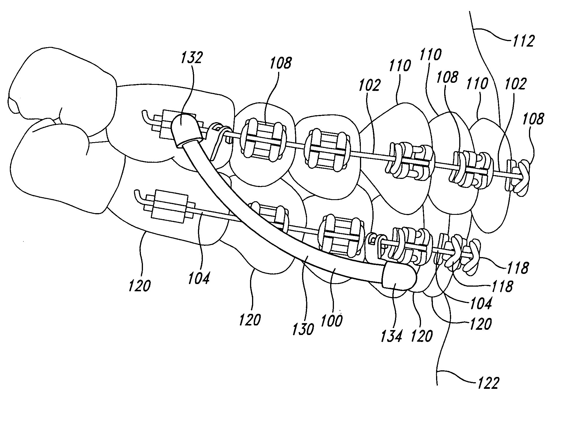
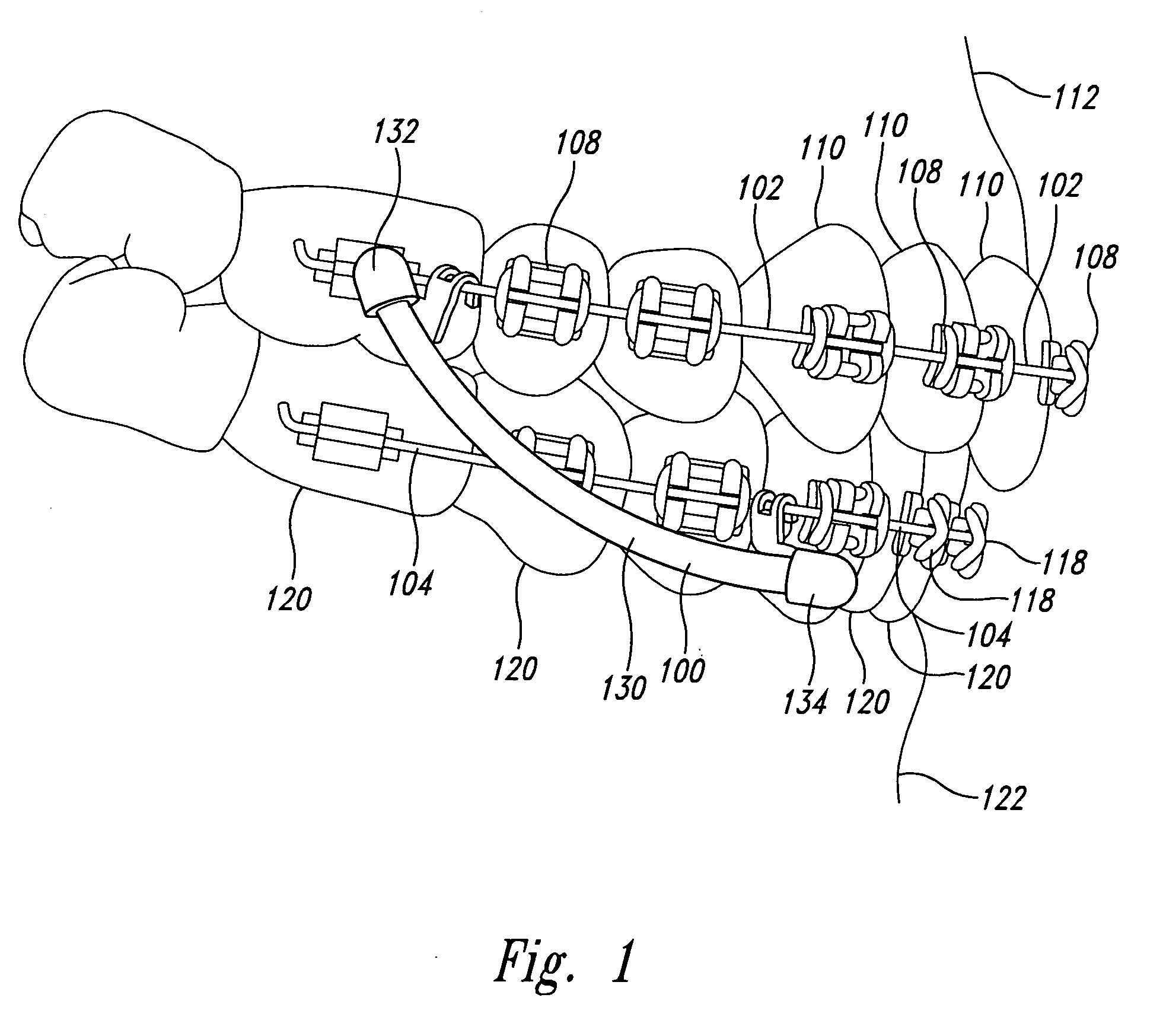
[0028] As will be discussed in greater detail herein, an orthodontic device disclosed herein can be easily clipped onto orthodontic wire such that the orthodontic device is retained on and fully supported by the orthodontic wire. As will be described in greater detail below, the device is easy to attach to the orthodontic wire but cannot be easily removed by the patient. However, the orthodontist can easily remove and replace the orthodontic device if necessary.

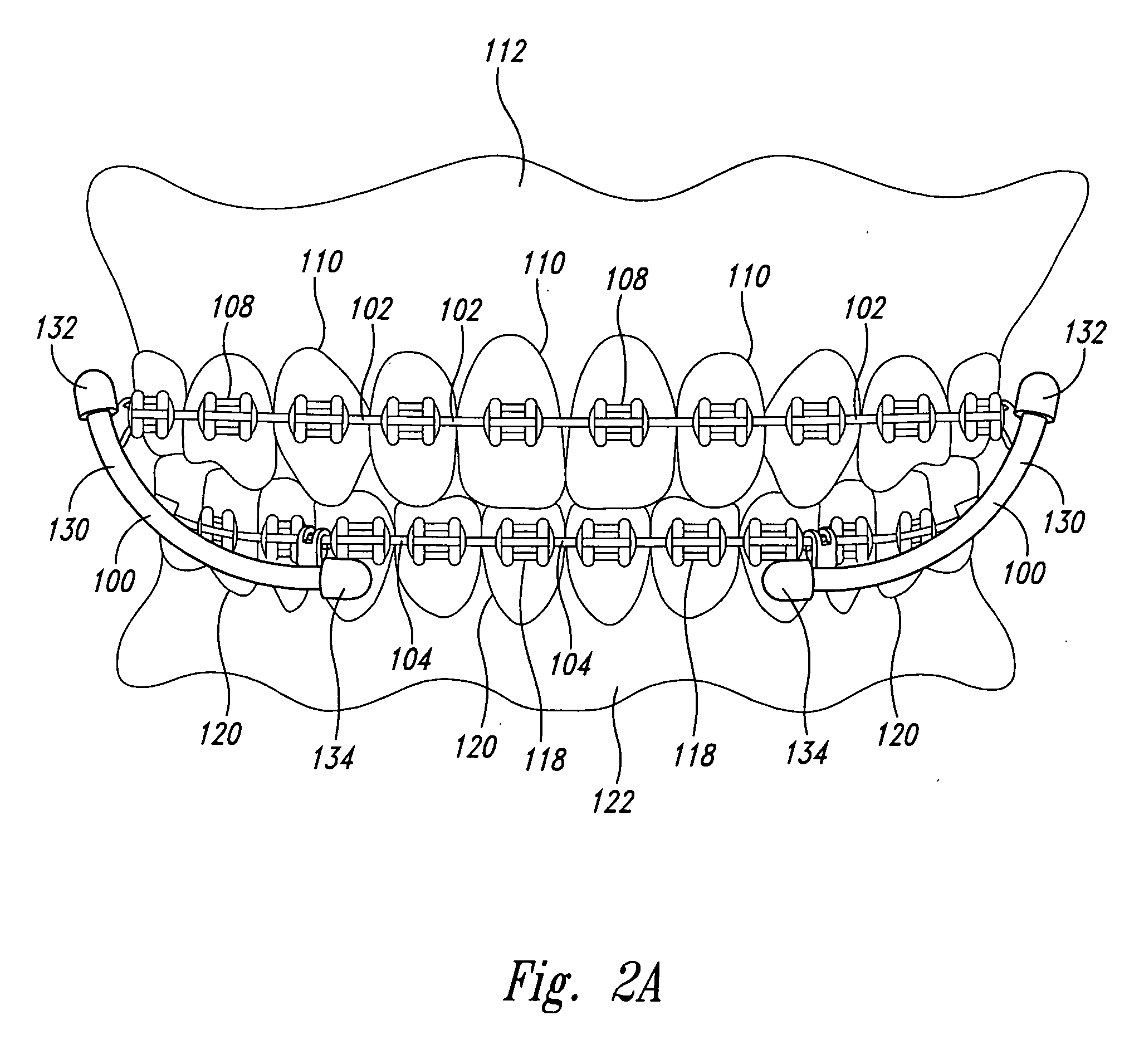
[0029]FIG. 1 illustrates the placement of an orthodontic device 100 onto orthodontic wire 102 and orthodontic wire 104. As illustrated in FIG. 1, brackets 108 are bonded directly to teeth 110 on an upper dental arch 112 of the patient. Similarly, brackets 118 are bonded directly to teeth 120 of a lower dental arch 122 of the patient. The brackets 118 on the upper arch 112 are coupled together by orthodontic wire 102, sometimes referred to as arch wire. The arch wire 102 extends through slots in each of the brackets 108. Simi...


PUM


Abstract

An orthodontic device allows direct attachment to orthodontic wires. A force module central portion is coupled to upper and lower end caps. The end caps have clip members that permit direct clipping onto the orthodontic wires to thereby retain the force module on the orthodontic wires. The clip members comprise first and second spaced apart curved members curving in a first direction and an intermediate curved member curving in the opposite direction. One or more of the curved members may flex to allow passage of the orthodontic wire. Alternatively the curved members have different radii of curvature to form a gap that is slightly smaller than the expected size of the orthodontic wire to permit the orthodontic wire to be forced between the gap and retained within a receiver portion formed by the curved members.

Description

BACKGROUND OF THE INVENTION [0001] 1. Field of the Invention [0002] The present invention is directed generally to orthodontics and, more particularly, to an orthodontic device for attachment to orthodontic wires. [0003] 2. Description of the Related Art [0004] The use of orthodontic devices, such as braces, is well known in the art. In the past, orthodontic devices required a significant number of metal components wrapped around individual teeth and wire interconnecting the various attachments. This approach was expensive and cumbersome as well as aesthetically unappealing. [0005] With the introduction of powerful adhesives, braces can be implemented with brackets and wire. The brackets can be bonded directly to the surface of individual teeth. The brackets are coupled together with guide wires, often referred to as arch wires. This less obtrusive approach permits the replacement of individual brackets that have broken or become dislodged. In addition, the brackets, elastic modules...

Claims


Application Information

Patent Timeline
Patent Type & Authority Applications(United States)
IPC IPC(8): A61C3/00
CPCA61C7/36A61C7/22
Inventor CACCHIOTTI, DINO A.CACCHIOTTI, LAWRENCE F.
Owner CACCHIOTTI DINO A
Why Eureka
Try Eureka