Dual rod cross connectors and inserter tools

a cross connector and inserter tool technology, applied in the field of spinal fixation devices, can solve the problems of increasing manufacturing costs, difficult fixation of cross connectors to spinal rods, and mounting difficulties of cross connectors

Active Publication Date: 2006-03-16
DEPUY SPINE INC (US)
View PDF99 Cites 126 Cited by
  • Summary
  • Abstract
  • Description
  • Claims
  • Application Information

AI Technical Summary

Benefits of technology

[0012] The present invention also provides a method for connecting first and second spinal fixation rods that includes the steps of coupling first and second spinal fixation rods to one or more vertebrae in a patient's spinal column, positioning a spinal cross connector relative to the first and second spinal fixation rods such that the first spinal fixation rod is seated within a first rod-rece

Problems solved by technology

While current spinal cross connectors have proven effective, difficulties have been encountered in mounting the cross connectors, and maintaining them in a desired position and orientation with respect to the spinal rod, or other spinal fixation device to which they are attached.
In particular, the clamp asse

Method used


Image

  • Dual rod cross connectors and inserter tools
  • Dual rod cross connectors and inserter tools
  • Dual rod cross connectors and inserter tools

Examples


Embodiment Construction

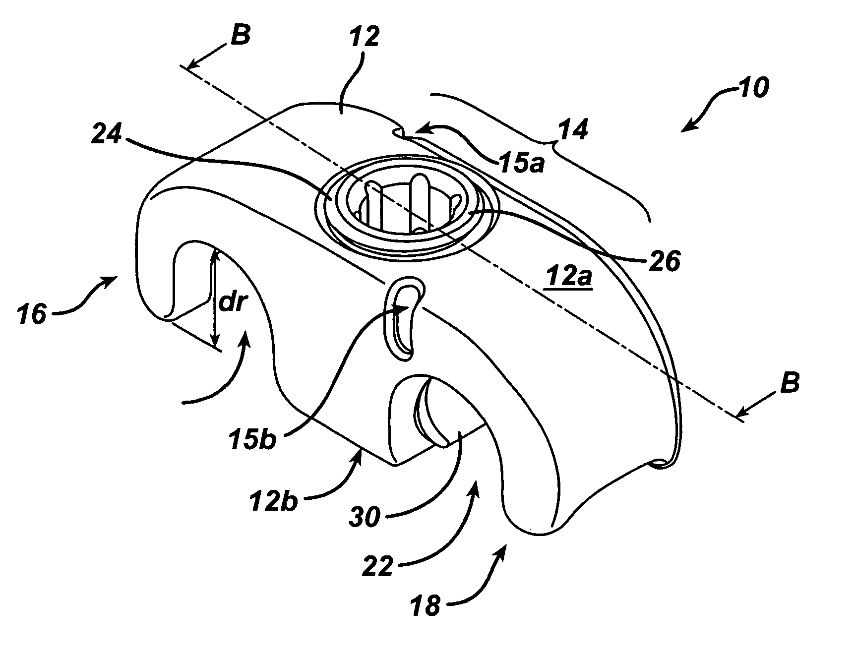
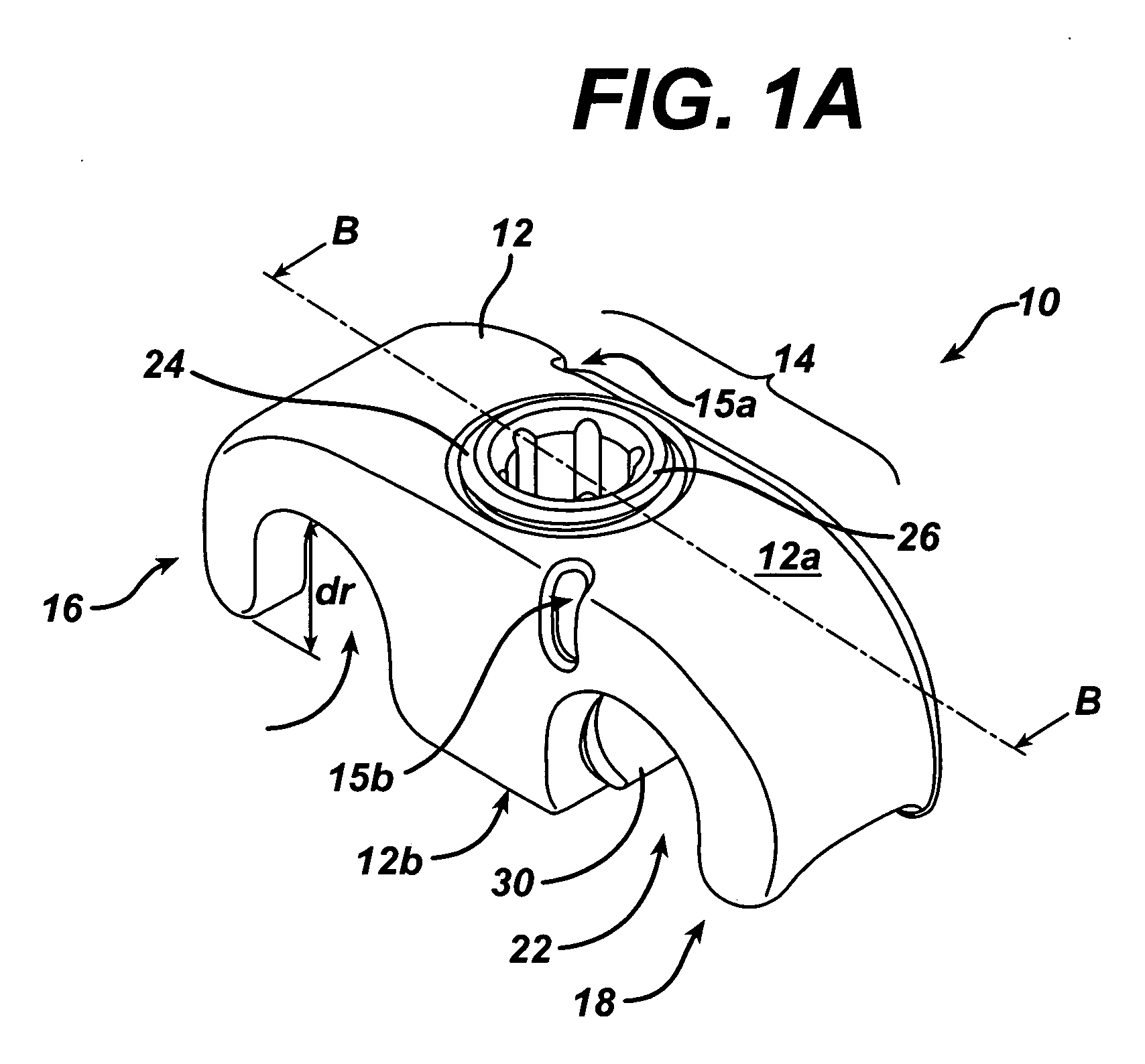
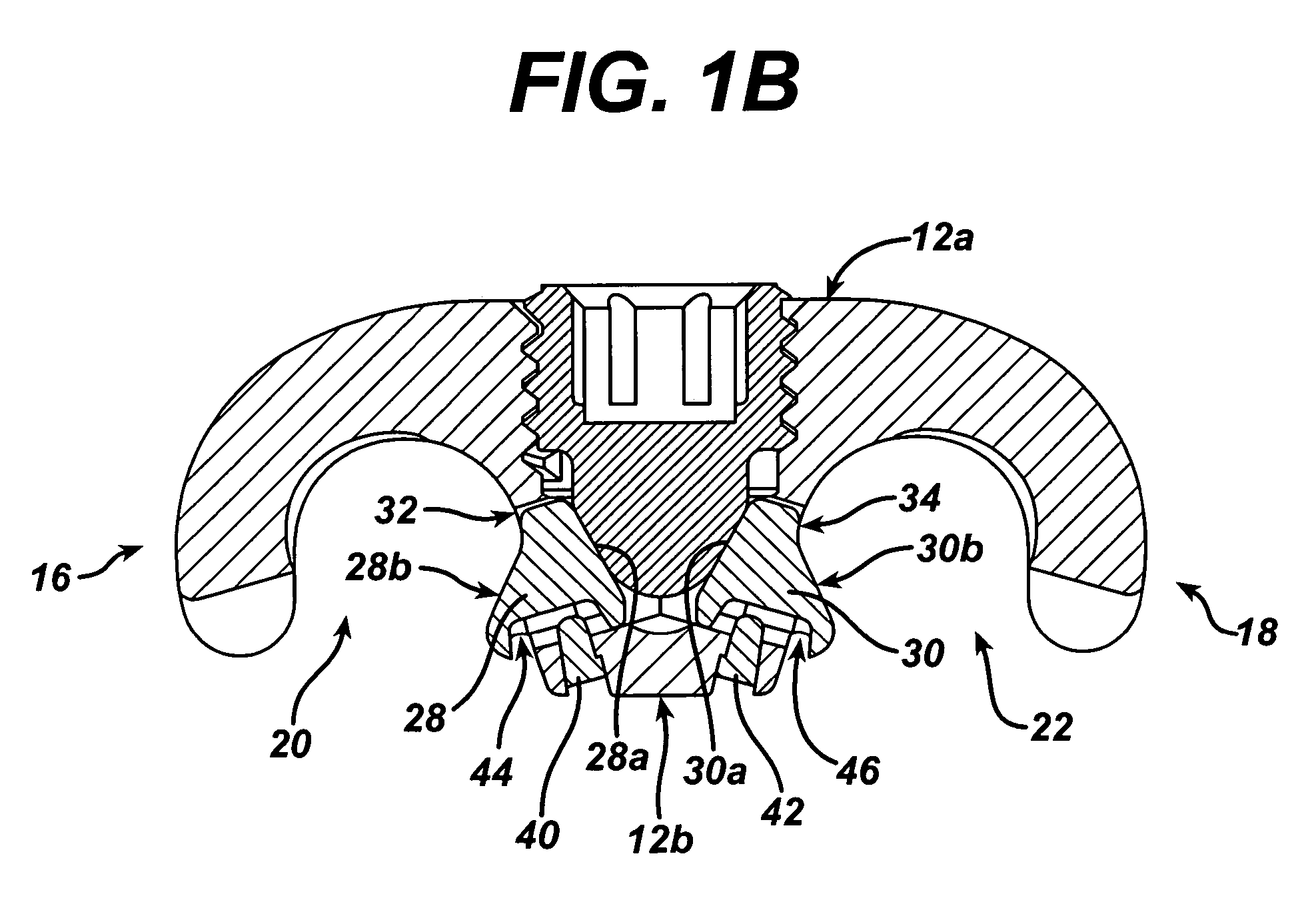
[0024] The present invention provides a spinal cross connector for connecting one or more spinal fixation elements, and more preferably for connecting two spinal fixation rods, that are implanted within a patient's spinal system. In general, an exemplary cross connector in accordance with the present invention includes an elongate body with at least one rod-receiving recess formed therein, and a locking mechanism that is adapted to couple to the elongate body and that is effective to lock a spinal fixation rod within the rod-receiving recess(es).

[0025] A person skilled in the art will appreciate that while the cross connector 10 is described herein as being adapted to engage a spinal fixation element, and in particular a spinal fixation rod, that a cross connector of the present invention can be configured to engage a variety of spinal fixation elements, such as anchors, cables, fixation plates, etc. Moreover, the cross connector can include only one rod-receiving recess for engagi...


PUM


Abstract

An implantable spinal cross connector is provided for connecting one or more spinal fixation devices, and more preferably for connecting two spinal fixation rods that are implanted within a patient's spinal system. In general, an exemplary cross connector in accordance with the present invention includes an elongate body with at least one rod-receiving recess formed therein, and a locking mechanism that is adapted to couple to the elongate body and that is effective to lock a spinal fixation rod within the rod-receiving recess(es). The present invention also provides an inserter tool to facilitate implanting a spinal implant or device, such as a spinal cross connector.

Description

FIELD OF THE INVENTION [0001] The present invention relates to spinal fixation devices, and in particular to a cross connector for connecting spinal fixation elements, such as spinal fixation rods, implanted in a patient's spinal system, and to tools for implanting the same. BACKGROUND OF THE INVENTION [0002] Spinal fixation devices are used in orthopedic surgery to align and / or fix a desired relationship between adjacent vertebral bodies. Such devices typically include a spinal fixation element, such as a relatively rigid fixation rod, that is coupled to adjacent vertebrae by attaching the element to various anchoring devices, such as hooks, bolts, wires, or screws. Alternatively, two rods can be disposed on the lateral or anterior surface of the vertebral body in a substantially parallel relationship. The fixation rods can have a predetermined contour that has been designed according to the properties of the target implantation site, and once installed, the rods hold the vertebrae...

Claims


Application Information

Patent Timeline
IPC IPC(8): A61B17/70
CPCA61B17/7049A61B17/7083A61B17/705
Inventor KIM, DANIEL HUANMICHIELLI, MICHAEL CARL
Owner DEPUY SPINE INC (US)
Why Eureka
Try Eureka