Connector

a technology of connecting rods and connectors, applied in the direction of coupling device connections, securing/insulating coupling contact members, electrical devices, etc., to achieve the effect of avoiding interference with the stabilizer

Active Publication Date: 2006-03-23
SUMITOMO WIRING SYST LTD
View PDF11 Cites 16 Cited by
  • Summary
  • Abstract
  • Description
  • Claims
  • Application Information

AI Technical Summary

Benefits of technology

[0007] The invention relates to a connector with a housing and at least one cavity in the housing for receiving a terminal fitting. A resilient lock is provided on an inner wall of the cavity and is engageable with the terminal fitting that has been accommodated in the cavity. A stabilizer projects from an outer surface of the terminal fitting and is received in an insertion groove in an inner wall of the cavity for guiding the terminal fitting into the cavity. The lock has a locking section that is engageable with an engaging section of the terminal fitting and an escaping recess that communicates with the insertion groove and permits entry of the stabilizer. The escaping recess is formed at a part of the lock behind the locking section and overlaps the locking section with respect to widthwise direction. Thus, interference with the stabilizer can be avoided, and it is not necessary to widen the connecting portion to avoid interference.
[0009] The locking preferably is engageable with an engaging section of the connecting portion over substantially the entire width. Thus, a terminal holding force increases and there is stronger against shear forces.
[0012] The engaging section preferably includes a rear end of the protrusion and the front edge of the locking hole. Thus, a wide area of engagement can be ensured between the engaging section and the locking section, thereby further increasing the terminal holding force.
[0013] The stabilizer preferably projects along a side plate on a lateral edge of a side of the projecting plate behind the locking hole. Thus, the escaping recess allows the stabilizer to escape, and interference with the lock can be avoided without increasing the width of the connecting portion.
[0014] The lock preferably is supported at both front and rear ends. Thus, the strength of the lock is enhanced.

Problems solved by technology

The lock and the stabilizer overlap and interfere with each other if the lock has substantially the same width over its entire length.

Method used


Image

  • Connector
  • Connector
  • Connector

Examples


Embodiment Construction

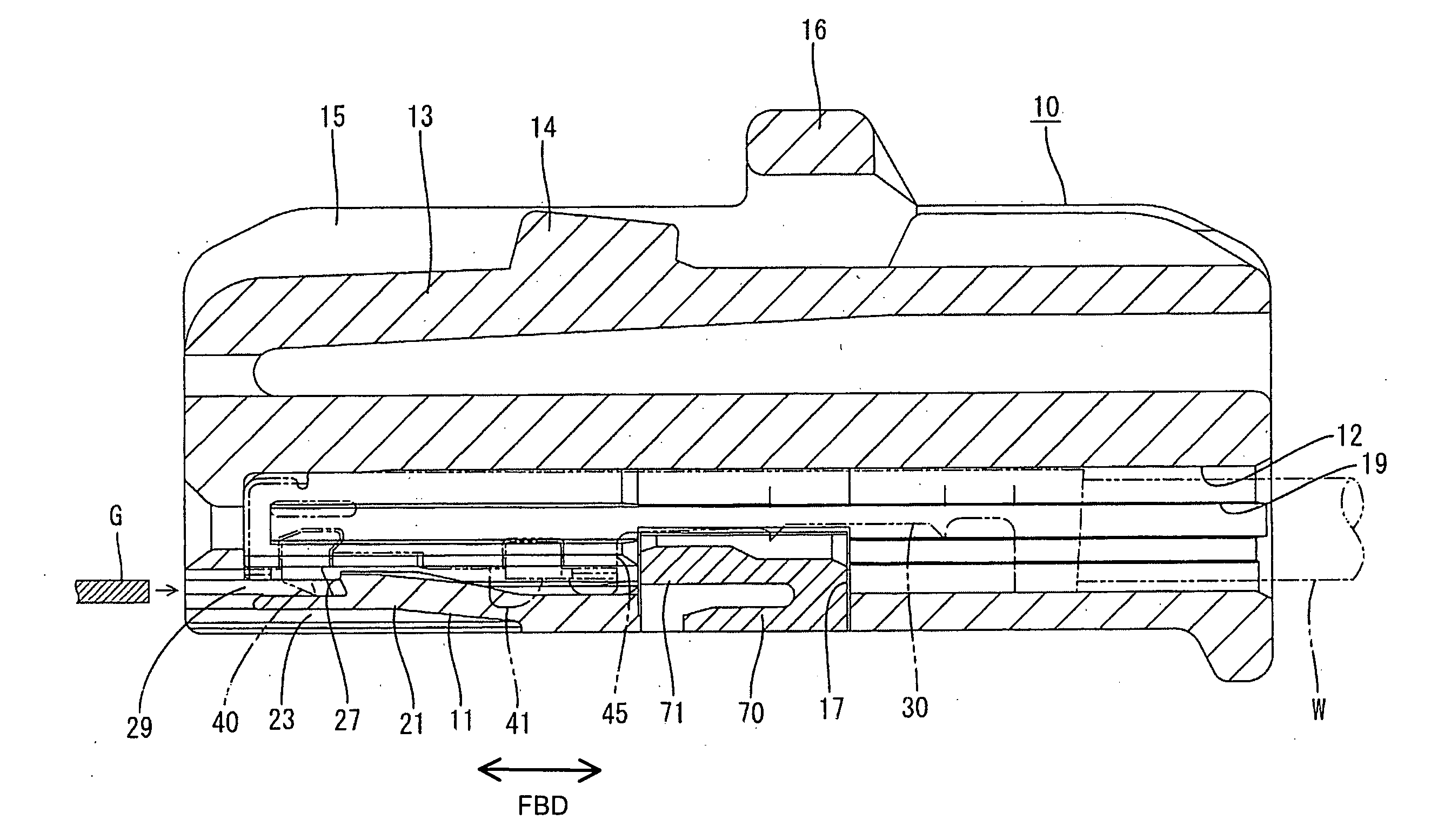
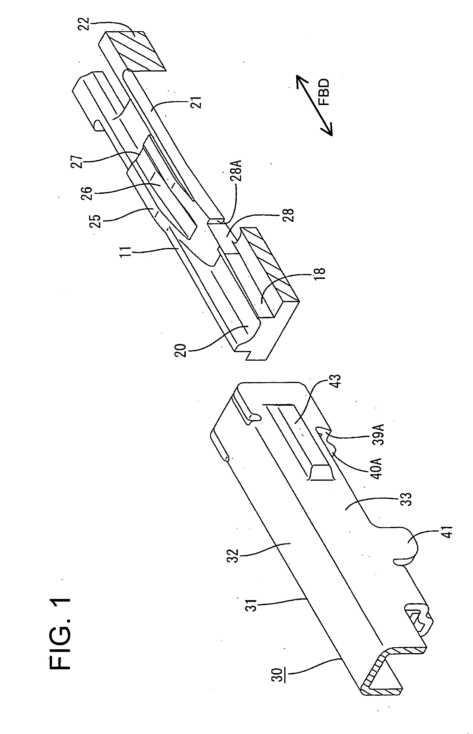
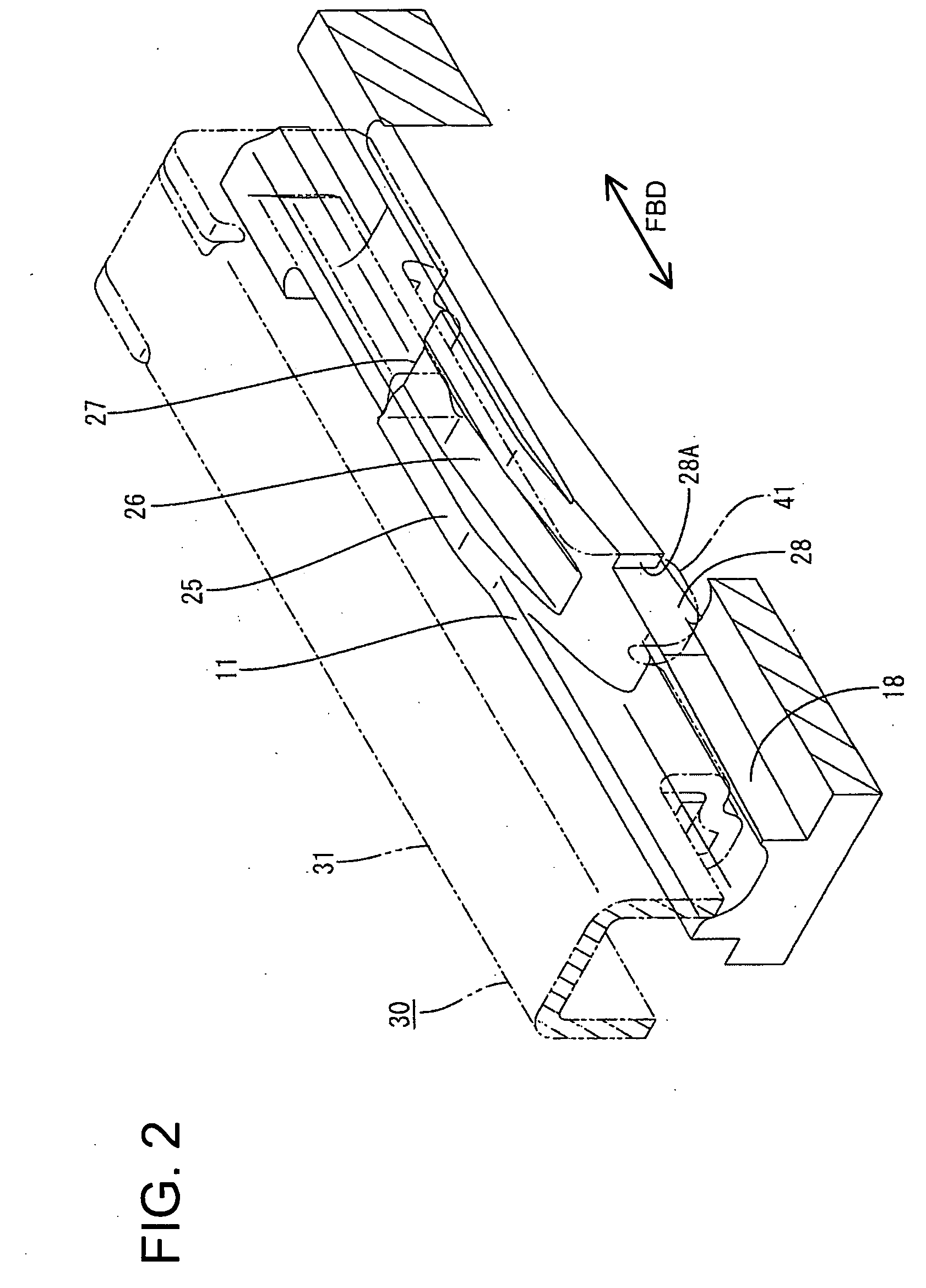
[0030] A connector according to the invention is illustrated in FIGS. 1 to 11. The connector has a female housing 10 that is connectable with a mating male connector housing (not shown). The connector also includes female terminal fittings 30 that are connectable with ends of wires W. In the following description, a side of the housing 10 to be connected with the mating housing is referred to as the front concerning forward and backward directions FBD.

[0031] Each terminal fitting 30 is formed by stamping or cutting a conductive metal plate into a specified shape and then bending, folding or embossing the metal plate shown in FIGS. 7 to 11. The terminal fitting 30 has a substantially box-shaped connecting portion 31 that is hollow in forward and backward directions FBD and a barrel 46 that is coupled behind the connecting portion 31. The barrel 46 includes front crimping pieces 47 that are configured to be crimped, bent or folded into connection with a core 91 of the wire W and rear...


PUM


Abstract

A terminal fitting (30) has a connecting portion (31) and a stabilizer (41) projects from an outer surface of the connecting portion (31). The stabilizer (41) is received in an insertion groove (18) in an inner wall of a cavity (12) for guiding the terminal fitting (30) into the cavity (12). A lock (11) is provided at the inner wall of the cavity (12) and has a locking section (27) engageable with an engaging surface (40A) of a protrusion (40) and a front edge (39A) of a locking hole (39) provided in the connecting portion (31). An escaping recess (28) is formed in a part of the lock (11) behind the locking section (27) and overlaps the locking section (27) with respect to a width direction. The escaping groove (28) communicates with the insertion groove (18) and receives the stabilizer (41).

Description

BACKGROUND OF THE INVENTION [0001] 1. Field of the Invention [0002] The invention relates to a connector. [0003] 2. Description of the Related Art [0004] U.S. Pat. No. 6,244,900 discloses a connector with a housing that has a cavity and a resilient lock that projects from an inner wall of the cavity. The connector also has a terminal fitting that is inserted into the cavity. A box-shaped connecting portion is provided at a front end of the terminal fitting, and a locking hole is formed in the connecting portion. A locking projection of the lock fits into the locking hole to lock the terminal fitting to lock the terminal fitting in the cavity. [0005] The width of the lock may be increased to increase an area of engagement of the lock with the front edge of the locking hole, and hence to increase a terminal fitting holding force. However, stabilizers project at the rear ends of outer surfaces of connecting portions of some terminal fittings for stabilizing the posture of the terminal ...

Claims


Application Information

Patent Timeline
Patent Type & Authority Applications(United States)
IPC IPC(8): H01R13/40H01R13/42H01R13/115H01R13/422H01R13/436
CPCH01R13/4362
Inventor TANAKA, TSUTOMUMASE, TSUYOSHI
Owner SUMITOMO WIRING SYST LTD
Why Eureka
Try Eureka