Method for controlling trajectory of robot

a robot and trajectory technology, applied in the direction of electric programme control, program control, instruments, etc., can solve the problems of difficulty in maintaining the orientation of the work tool relative to the ground, the prior art has problems, and it is difficult to carry out the teaching of maintaining the orientation of the work tool relative to the world coordina

Inactive Publication Date: 2006-03-30
FANUC LTD
View PDF5 Cites 39 Cited by
  • Summary
  • Abstract
  • Description
  • Claims
  • Application Information

AI Technical Summary

Benefits of technology

[0013] Accordingly, in relation to the above problems of the prior art, an object of the present invention is to provide a method for controlling the trajectory of a robot, by whic

Problems solved by technology

However, the above prior art has problems as described below.
However, in a playback operation, it is very difficult to desirably maintain the orientation of the work tool relative to the ground.
However, as a robot having the work tool 2 is a tracking robot, it is very difficult to carry out the teaching for maintaining the orientation of the work tool relative to the world coordinate system 10, unless a large number of teaching points are arranged such that the distance between each teaching

Method used


Image

  • Method for controlling trajectory of robot
  • Method for controlling trajectory of robot
  • Method for controlling trajectory of robot

Examples


first embodiment

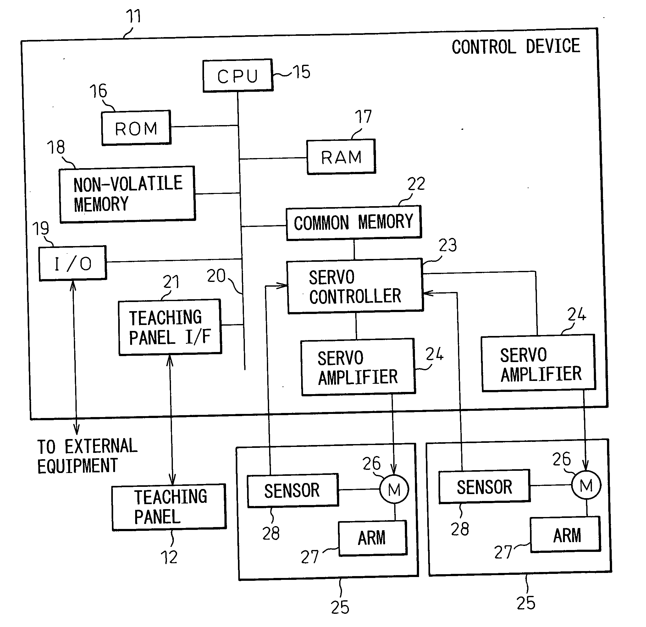
[0045] First, FIG. 4 shows a schematic configuration of a system used for a The system includes a multi-joint robot 1 of six-degree of freedom having a welding torch as a work tool 2, a multi-joint robot 6 of six-degree of freedom gripping a workpiece 4 to be welded and a control device 11 for controlling the robots 1 and 6. A teaching panel 12 for teaching operation is connected to the control device 11.

[0046] As coordinate systems for controlling the trajectory of the robot, some coordinate systems are defined as below: a first referential coordinate system 13 fixed to a base of the robot 1, indicating a reference point of the robot 1 having the tool 2, uniquely determined by a location of the robot 1; a second referential coordinate system 14 fixed to a base of the robot 6, indicating a reference point of the robot 6 gripping the workpiece 4, uniquely determined by a location of the robot 6; a first coordinate system 3 set on the tool 2 and moving with the tool 2, indicating the...

second embodiment

[0080] In the second embodiment relates to the motion by manual feeding. As shown in FIG. 13, the first coordinate system 3 set on the tool 2 attached to the leading robot 1 is orthogonally moved relative to the first referential coordinate system 13 of the leading robot 1 by the manual feed.

[0081] Corresponding to such a manual feed, the second coordinate system 5 set on the workpiece 4 gripped by the tracking robot 6 may be controlled such that the position and the orientation of the second coordinate system 5 is maintained relative to the first coordinate system 3 set on the tool 2. The control method in this embodiment is basically the same as the playback operation of the program, except that the command for moving the leading robot 1 is based on a command from the teaching panel 12, not on the teaching program. Therefore, the procedure in the second embodiment may be indicated by a flowchart as shown in FIG. 14.

[0082] In case of the manual feed, the robot is activated by push...

third embodiment

[0083] In the invention, as shown in FIG. 15, the tracking robot 6 is controlled such that the second coordinate system 5 set on the workpiece 4 gripped by the robot 6 is desirably translated (in the direction 1) and rotated (in the direction 2) by the manual feed, relative to the first coordinate system 3 set on the tool 2 of the leading robot 1. The feature of this embodiment is that the coordinate system serving as a referential coordinate system for the motion of the tracking robot 6 is set on the tool 2 attached to the leading robot 1. The procedure in the embodiment may be the same as that shown in FIG. 14. However, regarding step S705 for the interpolative motion, the relative position data is calculated based on the appointed direction of the motion by operating the manual feed button in step S503 in FIG. 11 or step S603 in FIG. 12.

[0084] The fourth embodiment of the invention includes, as shown in FIG. 16, a plurality of the tracking robots 6 of the first embodiment in coop...


PUM


Abstract

A method for controlling the trajectory of a robot, in which, in the cooperative operation of a leading robot having a work tool and a tracking robot gripping a workpiece, the position and the orientation of the work tool may be desirably controlled, even when the interpolative motion is carried out. The robots are cooperatively controlled such that the position and the orientation of a first tool coordinate system set on the work tool attached to the leading robot is moved along a desired trajectory on a second tool coordinate system set on the workpiece gripped by the tracking robot. During a playback operation after a teaching operation, the interpolative position data of the tracking robot is calculated by using the interpolative position data of the leading robot and the relative positions and the relative orientations data of the robots. The invention may be applied to a manual feed. The trajectory may be smoothed by filtering the interpolative position data.

Description

BACKGROUND OF THE INVENTION [0001] 1. Field of the Invention [0002] The present invention relates to a method for controlling a trajectory of a robot when a plurality of robots are operated by a cooperative control. For example, in the case of a welding operation by a cooperative control, the present invention relates to a method for obtaining the desired trajectories of a robot having a welding torch and a robot holding a workpiece to be welded. [0003] 2. Description of the Related Art [0004] Recently, an operation which cannot be carried out by one robot is carried out by a “cooperative control” in which a plurality of robots are controlled such that the plurality of robots cooperate. Typically, by the cooperative control of a robot holding a welding torch and a robot holding a workpiece to be welded, welding may be carried along a predetermined trajectory or a welding line on the workpiece. For such a cooperative control, in prior art as disclosed in Japanese Patent Publication N...

Claims


Application Information

Patent Timeline
IPC IPC(8): G06F19/00B25J9/10G05B19/18G05B19/4093
CPCB25J9/1682
Inventor KATO, TETSUAKITSUCHIDA, YUKINOBUNAGAYAMA, ATSUOICHINOSE, MASAKAZUHAMADA, TOSHIKO
Owner FANUC LTD
Why Eureka
Try Eureka