Wireless video surveillance system and method with remote viewing

a video surveillance and wireless technology, applied in the field of surveillance technology and equipment, can solve the problems of difficult installation and operation of wired devices, time-consuming, costly, etc., and achieve the effect of ensuring the security of wireless systems, and reducing the cost of installation and operation

Inactive Publication Date: 2006-03-30
GRAHAM TOMMY +9
View PDF42 Cites 98 Cited by
  • Summary
  • Abstract
  • Description
  • Claims
  • Application Information

AI Technical Summary

Benefits of technology

[0024] Still another aspect of the present invention is to provide methods of using the system embodiments set forth herein, such as a method for remote viewing by a remote viewing device in communication between at least one wireless input capture device ICD(s) and a corresponding digital input recorder (DIR), preferably via a RSC, including the steps of providing base system; at least one user accessing the DIR via user interface either directly or remotely; the DIR searching for signal from the ICD(s) and establishing communication with them; and locking the ICDs to send wireless data exclusively to that DVR; and / or the DVR locking itself for exclusive communication with the locked ICDs, thereby providing a secure surveillance system for a target environment.

Problems solved by technology

While video surveillance systems have existed in the prior art, typically they are wired devices that are difficult, time-consuming, and costly to install and operate.
Also, generally, they do not provide for wireless systems that are secure from wireless interception or Internet enabled interception and permit remote user access for viewing, reviewing stored information, and controlling the system's components, in particular via Internet connection to a remote controller computer or cellular phone or other Internet connected device.

Method used


Image

  • Wireless video surveillance system and method with remote viewing
  • Wireless video surveillance system and method with remote viewing
  • Wireless video surveillance system and method with remote viewing

Examples


Embodiment Construction

[0034] In the following description, like reference characters designate like or corresponding parts throughout the several views. Also in the following description, it is to be understood that such terms as “forward,”“rearward,”“front,”“back,”“right,”“left,”“upwardly,”“downwardly,” and the like are words of convenience and are not to be construed as limiting terms.

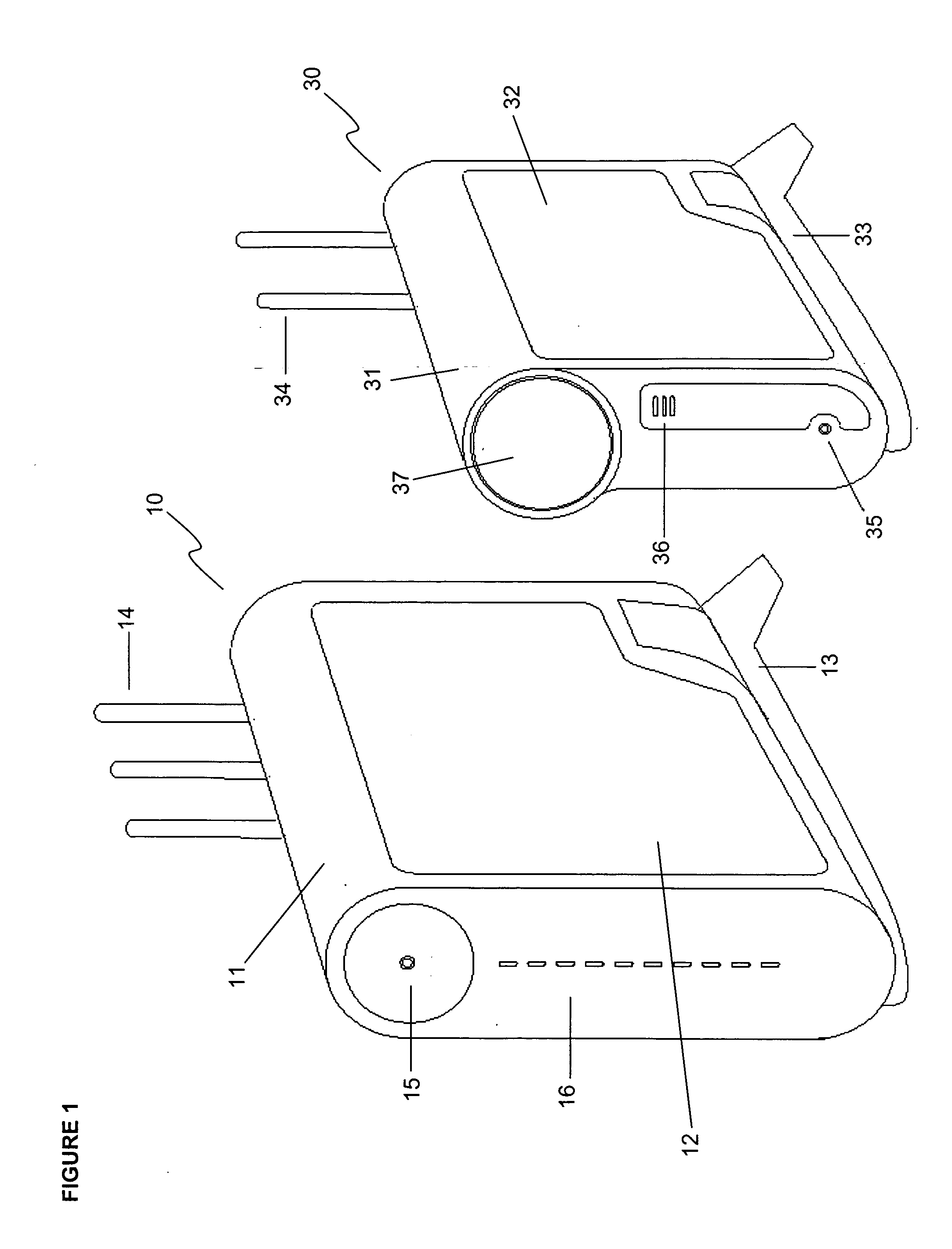
[0035] Referring now to the drawings in general, the illustrations are for the purpose of describing a preferred embodiment of the invention and are not intended to limit the invention thereto. As best seen in FIG. 1, the two base elements of a system constructed according to the present invention are shown side-by-side, including a wireless input capture device and a corresponding digital input recorder.

[0036]FIG. 1 shows a perspective view of one embodiment constructed according to the present invention, showing an input capture device (“ICD”), generally referred to as 30, and a digital input recorder (“DIR”), general...


PUM


Abstract

A surveillance system and method for remote viewing of inputs associated with at least one wireless input capture device ICD(s) monitoring a target environment, and a corresponding digital input recorder (DIR) and/or another ICD, including the steps of providing base system and at least one user accessing the DIR or ICD(s) via user interface remotely from a remote viewing device.

Description

CROSS-REFERENCE TO RELATED APPLICATIONS [0001] This non-provisional utility patent application is related to one or more prior filed co-pending non-provisional applications: [0002] U.S. application Ser. No. ______, entitled “Wireless Video Surveillance System and Method With Two-Way Locking of Input Capture Devices,” filed on Sep. 23, 2004. [0003] U.S. application Ser. No. ______, entitled “Wireless video surveillance system & method with DVR-based querying,” filed on the same date herewith. [0004] U.S. application Ser. No. ______, entitled “Wireless Video Surveillance System and Method with Emergency Video Access,” filed on the same date herewith. [0005] U.S. application Ser. No. ______, entitled “Wireless video surveillance system & method with External Removable Recording,” filed on the same date herewith.BACKGROUND OF THE INVENTION [0006] (1) Field of the Invention [0007] The present invention relates generally to surveillance technology and equipment and, more particularly, to ...

Claims


Application Information

Patent Timeline
Patent Type & Authority Applications(United States)
IPC IPC(8): H04N7/173H04N7/18H04N9/47
CPCG08B13/19619G08B13/19621G08B13/19656G08B13/1966G08B13/19663H04N21/4227G08B13/1968G08B13/19682H04N7/185H04N21/4223G08B13/19673
Inventor RENKIS, MARTIN
Owner GRAHAM TOMMY
Why Eureka
Try Eureka