
Wireless surveillance system and method for 3-D visualization and user-controlled analytics of captured data

a video surveillance and data visualization technology, applied in the field of surveillance technology and equipment, can solve the problems of not teaching or disclosing the distinct association of the various inputs of the multiple cameras with each of the cameras themselves, and achieve the effect of simple setup and control

Active Publication Date: 2013-03-12
JOHNSON CONTROLS TYCO IP HLDG LLP
View PDF8 Cites 8 Cited by
  • Summary
  • Abstract
  • Description
  • Claims
  • Application Information

AI Technical Summary

Benefits of technology

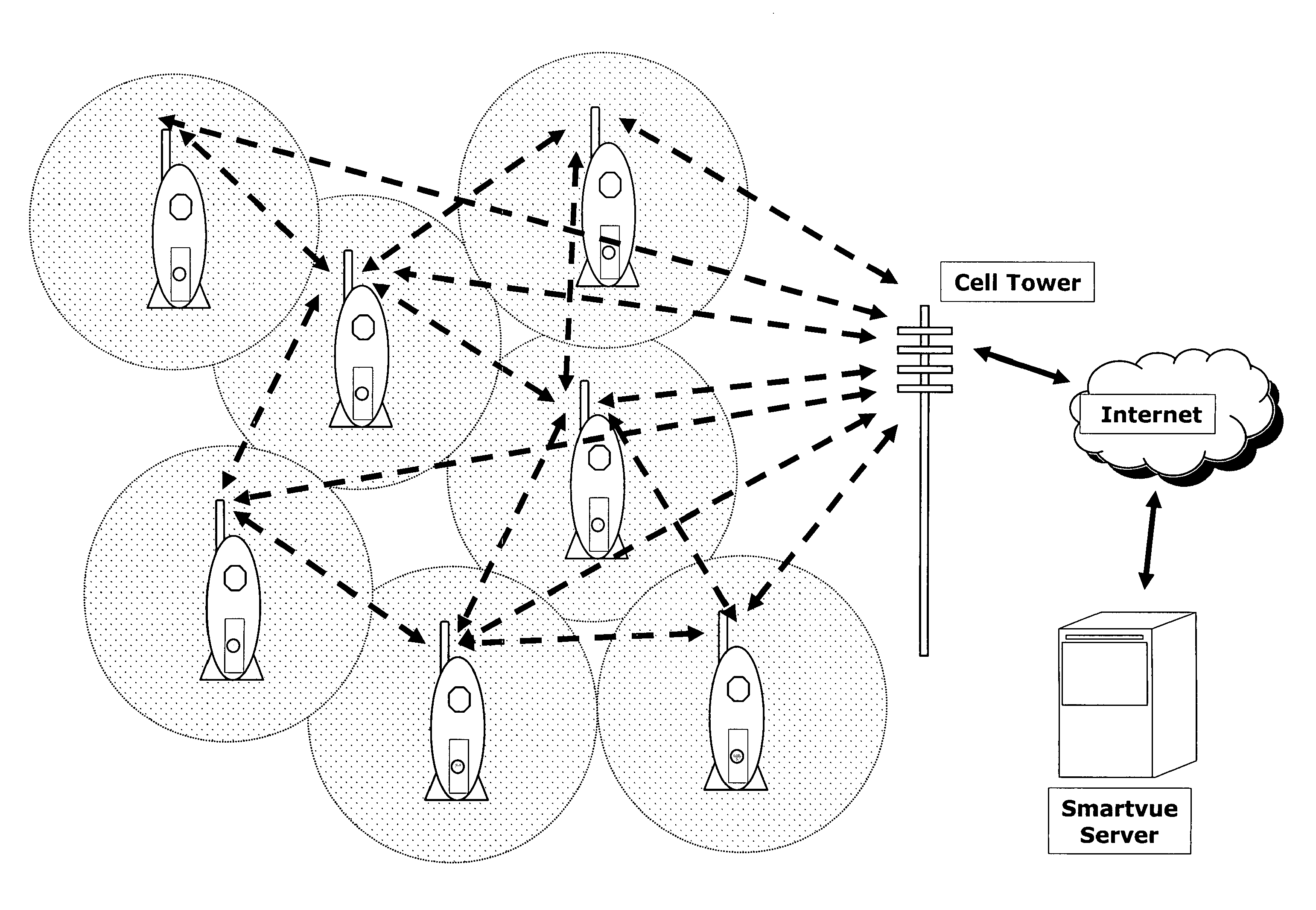
The present invention offers a wireless surveillance system with easy setup and controls for surveillance cameras and digital recording devices. The system provides a 3D model of a space and displays real-time information from the cameras, including location, settings, and environment conditions. The system also analyzes the data from the cameras and provides activity density based on the inputs. The invention allows for remote viewing and control of the cameras and recording devices using a server computer or internet access. Overall, the invention simplifies surveillance and analysis of target environments.

Problems solved by technology

US Patent Application Publication No. 2007 / 0052807 published Mar. 8, 2007 for System and Method for User Monitoring Interface of 3-D Video Streams from Multiple Cameras provides integration of video stream from multiple cameras but does not teach or disclose distinct association of the various inputs from the multiple cameras with each of the cameras themselves, including location, settings, environment conditions, etc.
These do not all provide for object tracking, but those that do focus on single object tracking, not teaching collective activity that is relevant to a target environment like retail, airport, etc.

Method used


Image

  • Wireless surveillance system and method for 3-D visualization and user-controlled analytics of captured data
  • Wireless surveillance system and method for 3-D visualization and user-controlled analytics of captured data
  • Wireless surveillance system and method for 3-D visualization and user-controlled analytics of captured data

Examples


Embodiment Construction

[0052]In the following description, like reference characters designate like or corresponding parts throughout the several views. Also in the following description, it is to be understood that such terms as “forward,”“rearward,”“front,”“back,”“right,”“left,”“upwardly,”“downwardly,” and the like are words of convenience and are not to be construed as limiting terms.

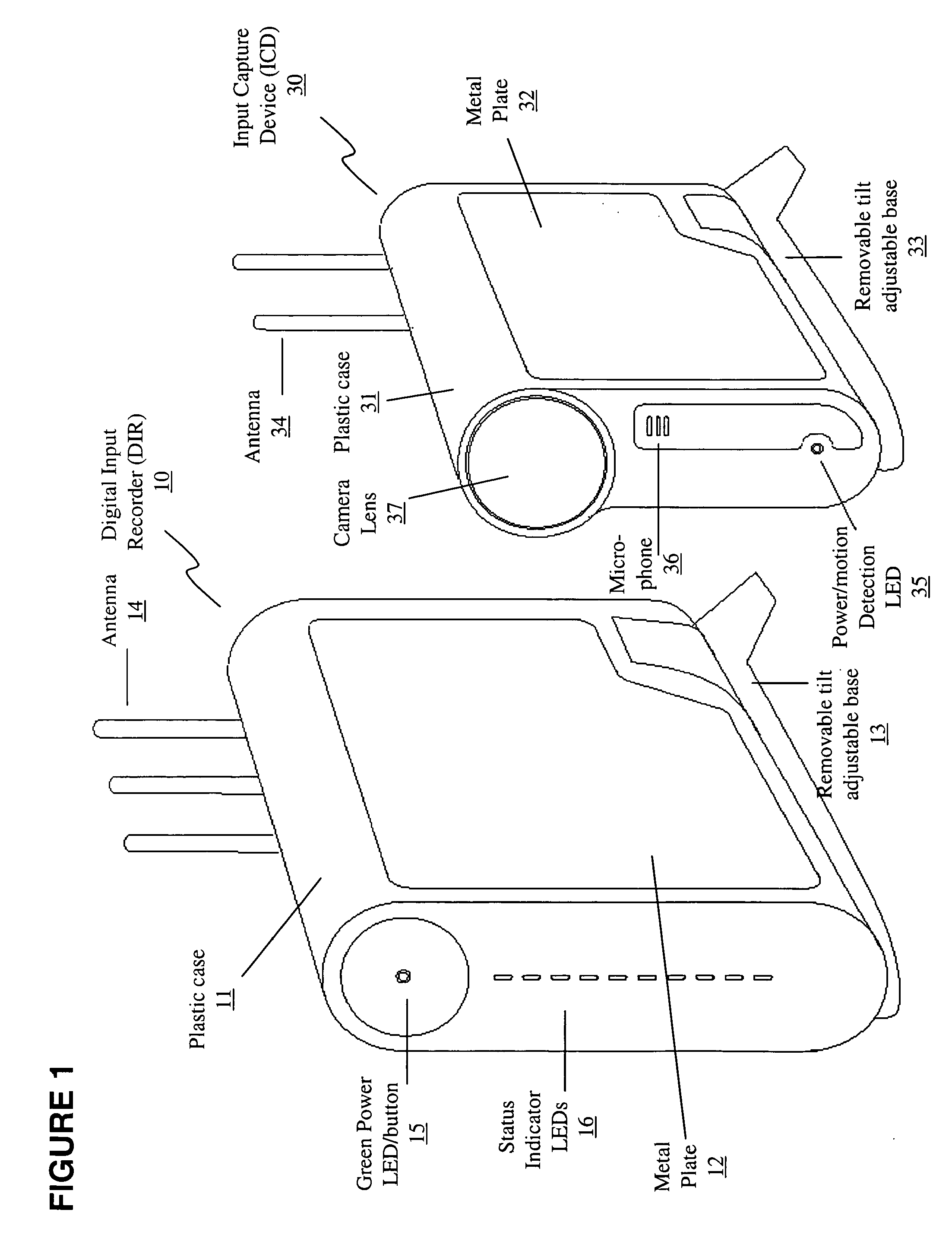
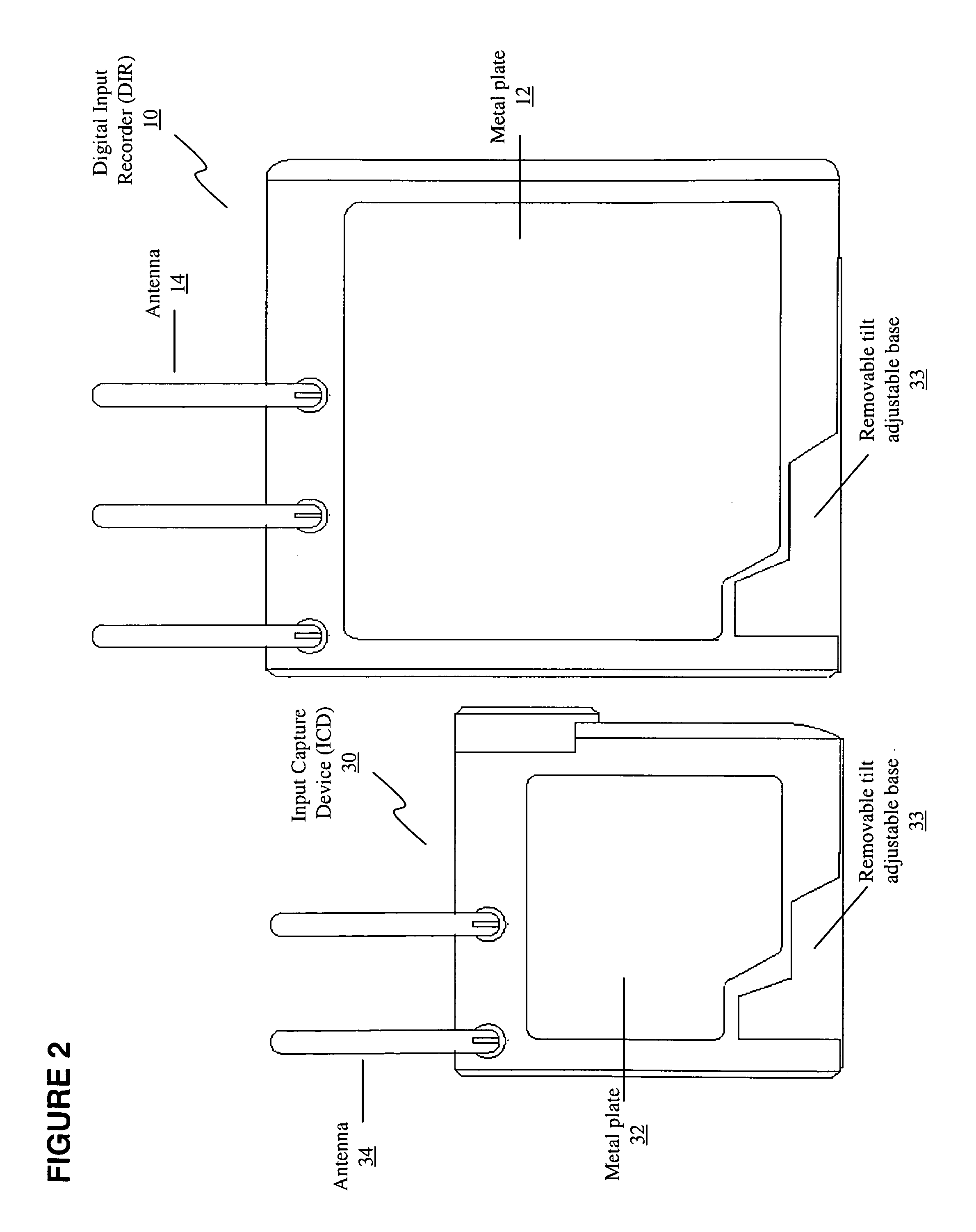
[0053]Referring now to the drawings in general, the illustrations are for the purpose of describing a preferred embodiment of the invention and are not intended to limit the invention thereto. As best seen in FIG. 1, the two base elements of a system constructed according to the present invention are shown side-by-side, including a wireless input capture device and a corresponding digital input recorder.

[0054]FIG. 1 shows a perspective view of one embodiment constructed according to the present invention, showing an input capture device (“ICD”), generally referred to as 30, and a digital input recorder (“DIR”), generally r...


PUM


Abstract

Systems and methods having a 3D model of a space provides a 3D context for the inputs from the ICDs; inputs from the ICDs, including direct cross-communication information, location, settings, environment conditions, and inputs (video, audio, temperature, other sensors), being visually represented on a GUI independently and in the 3D context for simultaneous display of all the info, and analytics based on the info, including activity density within the 3D context based on the inputs, for surveillance and analysis of target environment(s).

Description

CROSS-REFERENCE TO RELATED APPLICATIONS[0001]This non-provisional utility patent application claims the benefit of one or more priority documents, namely: it is a continuation-in-part from U.S. patent application Ser. No. 11 / 520,117, No. 2007 / 0009104 entitled Wireless Smart Camera System and Method filed Sep. 13, 2006; and U.S. Provisional Patent Application Ser. No. 61 / 068,003 filed Mar. 4, 2008; both of which are incorporated herein by reference in their entirety.[0002]Also, this non-provisional utility patent application is related to one or more prior filed co-pending non-provisional applications:[0003]U.S. application Ser. No. 10 / 948,501, entitled “Wireless Video Surveillance System and Method With Two-Way Locking of Input Capture Devices,” filed on Sep. 23, 2004.[0004]U.S. application Ser. No. 10 / 949,487 entitled “Wireless Video Surveillance System & Method with DVR-Based Querying,” filed on Sep. 24, 2004.[0005]U.S. application Ser. No. 10 / 949,609 entitled “Wireless Video Surv...

Claims


Application Information

Patent Timeline
IPC IPC(8): H04N7/18
CPCG08B13/19656G08B13/19682G08B13/19693G08B25/009H04N5/23203H04N5/23206H04N5/247H04N7/18H04N23/66H04N23/661H04N23/631H04N23/90
Inventor RENKIS, MARTIN A.
Owner JOHNSON CONTROLS TYCO IP HLDG LLP
Learn More