
Lid with bistably valved drinking spout

a valved drinking spout and lid technology, applied in the field of drinking containers, can solve the problems of unsanitary, messy, time-consuming, and unsanitary solution, and achieve the effect of convenient drinking

Inactive Publication Date: 2006-04-06
DIXIE CONSUMER PROD
View PDF23 Cites 112 Cited by
  • Summary
  • Abstract
  • Description
  • Claims
  • Application Information

AI Technical Summary

Benefits of technology

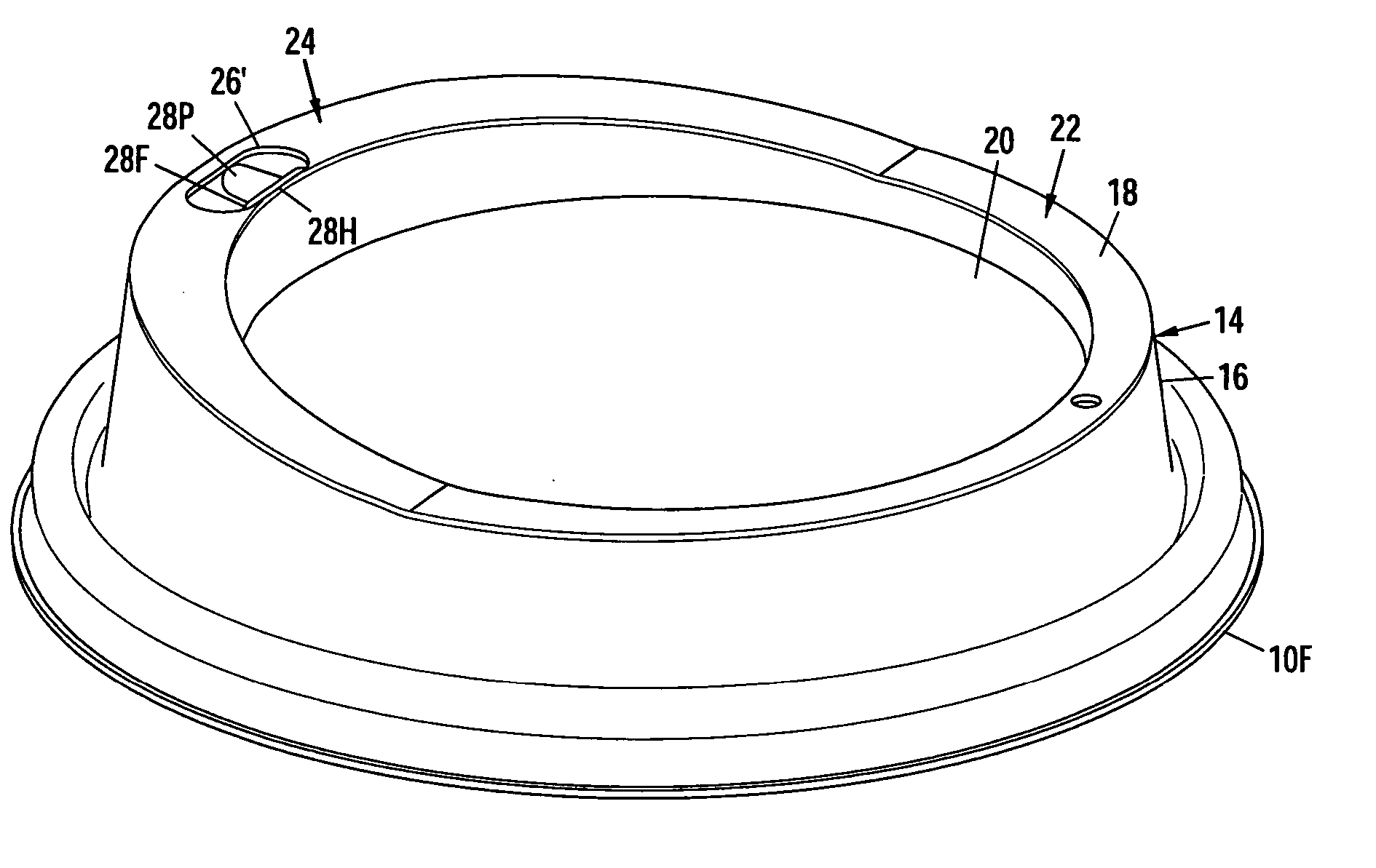
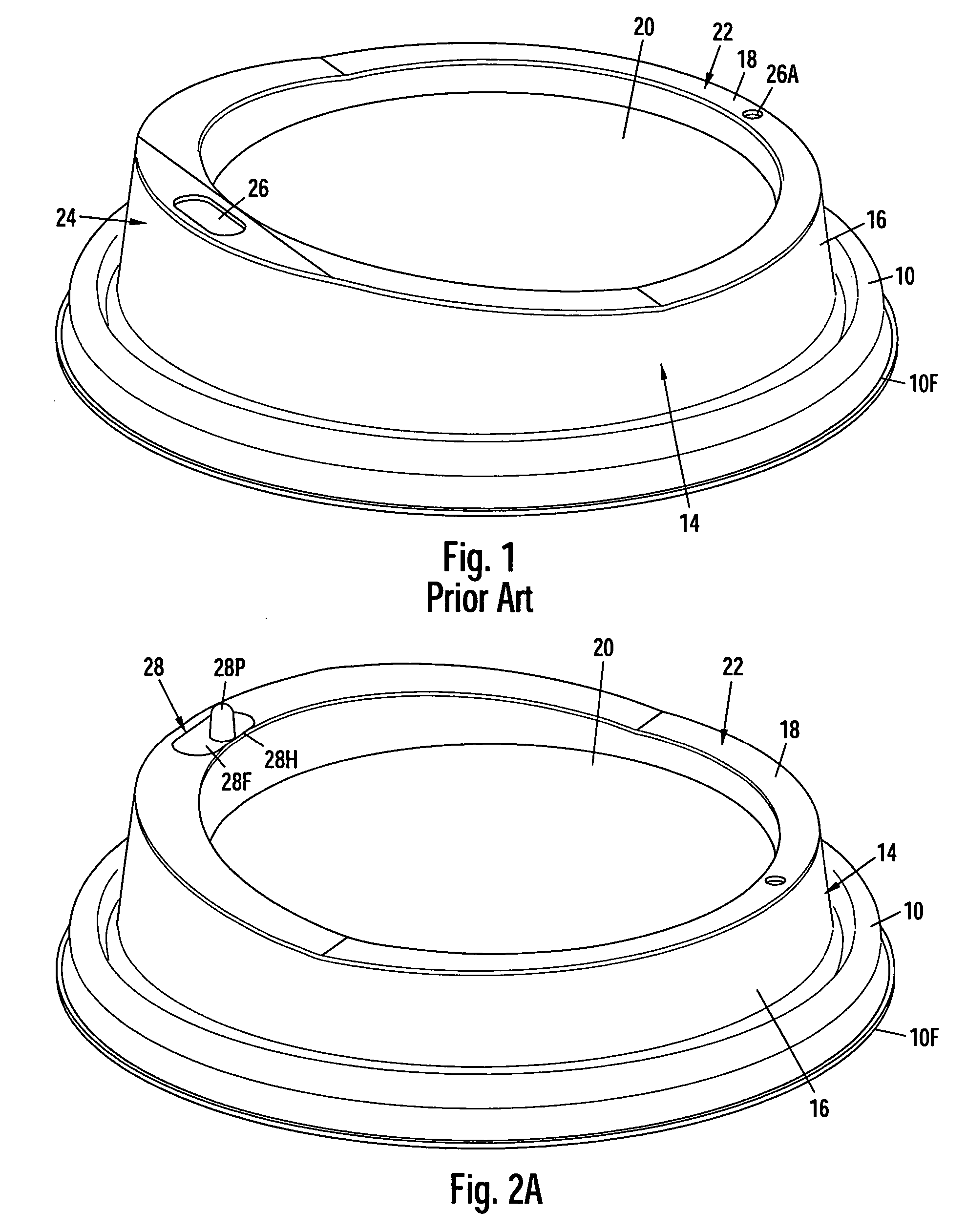
"The invention is a new and improved lid with a raised drink-through spout and a valved drink opening. The lid is made from one piece of material and has a mounting portion at its base with a resilient annular gripping groove. The lid also has an annular outer sidewall or turret with a central recess portion that forms a center panel of the lid. The turret has a raised drinking spout with a valve in the form of a rectangular flap in the top surface or ridge of the rim. The flap has an integrally formed upward protrusion or post and a hinge line along the back edge. The user can open the valve by applying downward force to the top of the post, causing the flap to bend downwardly at an angle from the ridge or surface of the rim. The user can then drink from the lid as normal by placing their lips around the raised drink spout. To re-close the valve, the user applies inward force to a point on the outer sidewall below the cut front edge. This causes the front wall to deflect inwardly and the cut front edge of the drink hole to distort outwardly, widening the hole. This releases the top edge of the post, allowing it to move upwardly so that the flap can spring back to its horizontal and closed position."

Problems solved by technology

Despite their success, one disadvantage is that the drink hole is always open.
This is problematic to people that want to purchase a beverage and then take it somewhere else, such as their office, to be consumed.
This solution is time consuming, messy, and unsanitary.
While an improvement over non-closable raised drink spout lids, these lids have not gained widespread use because the attached flexible arm is awkward and can interfere with the user when they attempt to drink from the cup.
After the plug is removed from the drink hole it is often wet with the beverage, which tends to drip from the plug onto the user's clothing.
Also, this type of lid uses more material and lid more difficult to make than a standard raised drink-through spout lid.
The operation of opening and closing the hole is cumbersome and requires two hands.
This takes more labor time at the service counter.
Because of these deficiencies, these types of lid have not gained widespread commercial acceptance or use.
While a functional improvement over the lids mentioned above, the two-piece construction is expensive to make.
Thus these lids have a significant cost disadvantage over the other prior-art lids discussed above.
The operation of this lid does not allow for a drink-through type drink spout popular with consumers and food-service operators alike.
These lids all have one or more disadvantages, including complexity, unreliability, costliness, difficulty of use, awkwardness, high cost, etc.
Thus, all present lids with raised drink-through spouts have various disadvantages: the beverage can to splash out and lose heat, tape is awkward to use and is not resealable, sealing plugs interfere with the user's drinking, drip the beverage within when opened, use a relatively large amount of material, and require excess time and labor to use, two-part lids are expensive to make and require excess material, and other lids are complex, unreliable, expensive, difficult to use, and awkward.
However, when the top edge of the post is pushed past the cut front or catch edge of the top wall, it will catch under this edge and lock the flap in an open position.

Method used


Image

  • Lid with bistably valved drinking spout
  • Lid with bistably valved drinking spout
  • Lid with bistably valved drinking spout

Examples


Embodiment Construction

—FIG. 1—PRIOR-ART LID

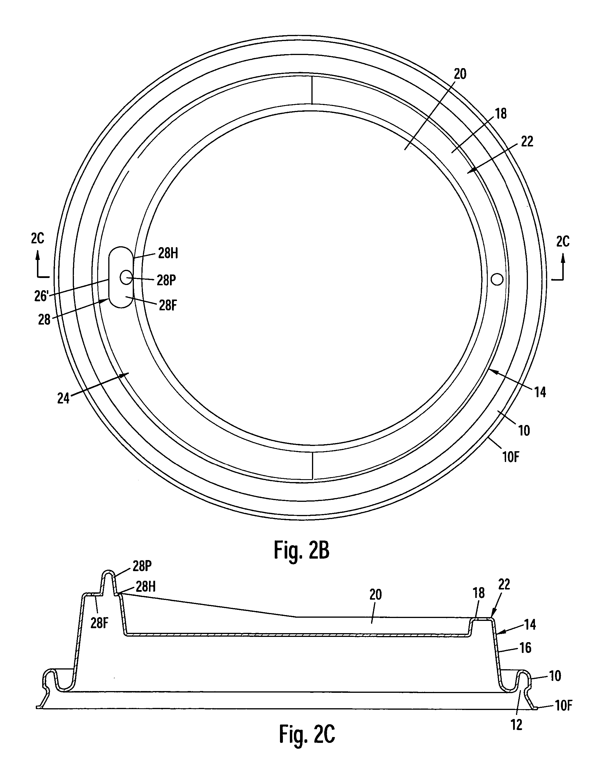
[0054]FIG. 1 shows a perspective view of a prior-art drink-through domed cup lid similar to the lid shown in the Sadlier et al. design patent, supra. This lid has an annular, bottom rim 10 which has a slight flange 10F extending out from its bottom. The underside of rim 10 forms a downwardly facing annular cup-rim-gripping and sealing groove 12 (best seen in FIG. 2C). A turret or domed portion 14 extends up from inside of groove 12; turret 14 has a truncated conical shape and has an annular vertical wall 16. Turret 14 has an annular top horizontal surface, or ridge 18 that extends in from the top of wall 16, and a recess 20 that is surrounded and below ridge 18. Thus wall 16, ridge 18, and recess 20 form an annular upper rim 22. Stated differently, rim 22 is the top portion of turret 14 and encircles and defines recess 20. The front half of rim 22 slopes upwardly and then levels off to form a raised or higher and wider drinking portion or spout 24 at the front. ...


PUM


Abstract

A lid with a raised drink-through spout (24) has a hinged flap valve (28) covering a drink opening (26′) formed in the surface of the spout. The user opens the valve by pushing the top of a post (28P) on the flap (28F) down. A hinge (28H) holding the flap urges the flap to return to its closed and horizontal orientation, but the top edge of the post will catch under a catch edge of the opening opposite the hinge. This holds the flap open. The user can then drink from the spout. To re-close the valve, the user applies inward force to the outer sidewall (16) below the catch edge. This causes the wall to deflect inwardly and the catch edge to distort outwardly, widening the hole. This releases the post, allowing it to move upwardly so that the flap can spring back to its horizontal and closed position.

Description

CROSS-REFERENCE TO RELATED APPLICATION [0001] This patent issued from an application that is a continuation of application Ser. No. 10 / 944,387, filed 2004 Sep. 17, now abandoned.BACKGROUND [0002] 1. Field of Invention [0003] This invention relates generally to drinking containers, specifically to valved lids for such containers. [0004] 2. Prior Art [0005] Fast food restaurants, beverage shops, and other food-service establishments serve hot beverages in disposable cups with lids or covers. The lids keep the cup's contents hot and prevent the liquid from spilling. Many lids have openings so the user can drink the beverage from the cup below without removing the lid. Some lids have raised drink-through spouts that allow the user to place both lips around the spout to more easily and safely sip the beverage. [0006] For example U.S. Pat. No. 4,589,569 to Clements (1986) discloses a dome lid with a raised and wide drink-through spout. An open drink hole is cut out of the top of the spout...

Claims


Application Information

Patent Timeline
Patent Type & Authority Applications(United States)
IPC IPC(8): B65D51/18A47G19/22
CPCB65D43/0218B65D47/06B65D47/2025B65D2543/00046B65D2543/00222B65D2543/00296B65D2543/00509B65D2543/00537B65D2543/00555
Inventor SADLIER, CLAUS E.
Owner DIXIE CONSUMER PROD
Learn More