
Defining interpolation filters for error concealment in a coded image

a technology of error concealment and interpolation filter, which is applied in the direction of color television with bandwidth reduction, signal generator with optical-mechanical scanning, and signal system with bandwidth reduction. it can solve the problems of spatial concealment techniques that rely on temporal error concealment techniques, coded video streams incur data loss or corruption, and spatial concealment techniques achieve lower performan

Inactive Publication Date: 2006-04-06
THOMSON LICENSING SA
View PDF3 Cites 112 Cited by
  • Summary
  • Abstract
  • Description
  • Claims
  • Application Information

AI Technical Summary

Problems solved by technology

Not infrequently, such coded video streams incur data losses or become corrupted during transmission because of channel errors and / or network congestion.
Upon decoding, the loss / corruption of data manifests itself as missing / corrupted pixel values that give rise to image artifacts.
Typically, at the same level of complexity, spatial concealment techniques achieve lower performance than temporal error concealment techniques that rely on information from other transmitted pictures.
When the spatial concealment yields a relatively poor intra-coded picture, each resultant inter-coded picture will likewise have poor quality.

Method used


Image

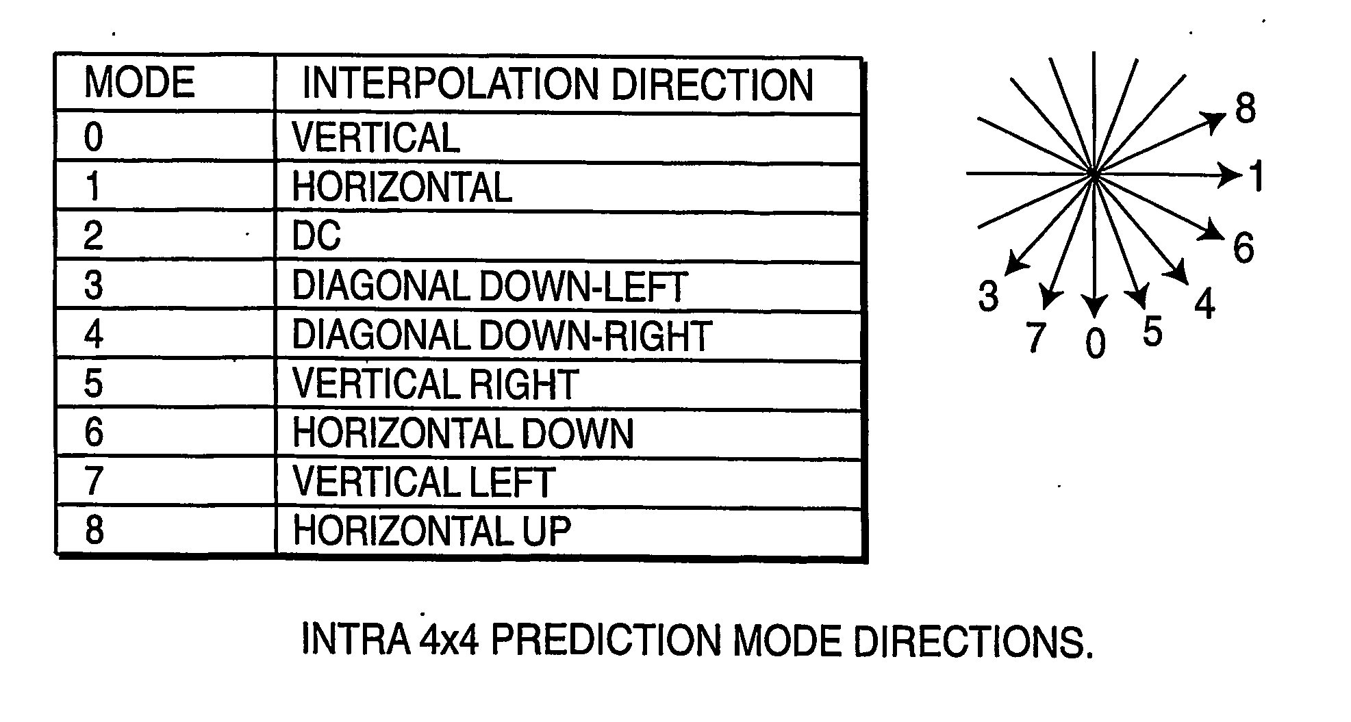
  • Defining interpolation filters for error concealment in a coded image
  • Defining interpolation filters for error concealment in a coded image
  • Defining interpolation filters for error concealment in a coded image

Examples


Embodiment Construction

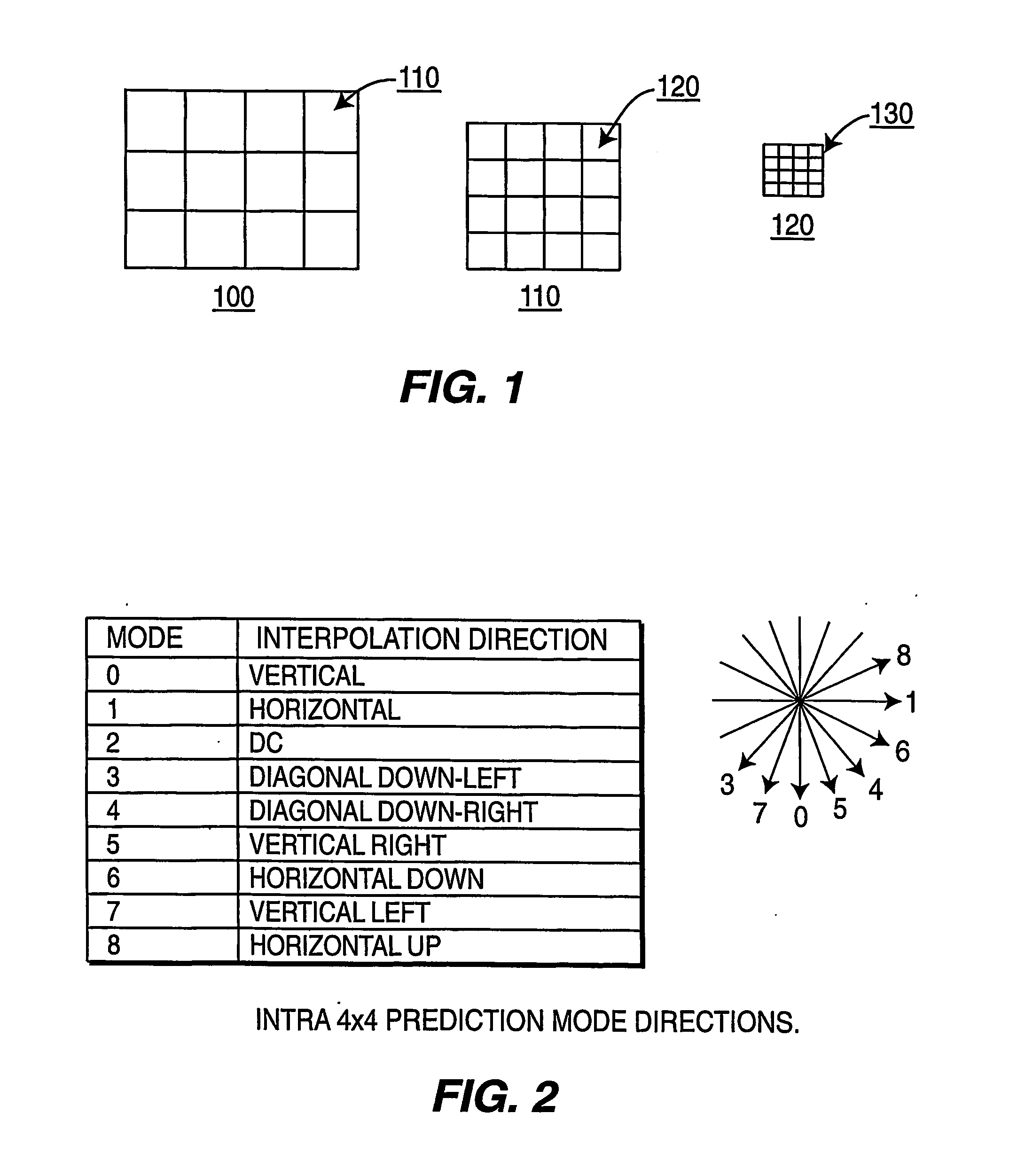
[0013] Block-based video compression techniques, such as embodied in the proposed ISO / ITU H.264 coding technique, operate by dividing a picture into slices, each slice comprising a set of macroblocks or macroblock pairs, with each macroblock coded in accordance with the coding technique. A macroblocks typically comprises a squared region of 16×16 pixels. For coding purposes, macroblocks can be further partitioned into sub-macroblocks not necessarily squared. Each sub-macroblock can have a different coding mode when the macroblock is encoded. For ease of discussion, a block will be referred to as a sub-macroblock of 4×4 pixels. FIG. 1 depicts the partitioning of a coded picture 100 into macroblocks 110, with each macroblock 110 partitioned into blocks 120, and each block partitioned into pixels 130. Note that the number of macroblocks within a picture varies depending on the size of the picture, while the number of blocks within a macroblock remains constant.

[0014] To reduce the cos...


PUM


Abstract

Concealment of errors in a coded image occurs by first selecting an inter-prediction mode in accordance with the coding of the image. The selected intra-prediction mode, while ordinarily used to specify the direction for obtaining a coding prediction value, also serves to specify the direction for obtaining estimated values for error concealment. An interpolation filter defines the manner of obtaining estimated pixel values along the direction specified by the intra-prediction mode. Like the intra-prediction mode, the interpolation filter is derived in accordance with the coding of the image. Concealment of the image is achieved using the estimated values obtained in the manner prescribed by the interpolation filter.

Description

CROSS REFERENCE TO RELATED APPLICATION [0001] This application claims priority under 35 U.S.C. 119(e) to U.S. Provisional Patent Application Ser. No. 60 / 439,185 filed Jan. 10, 2003, the teachings of which are incorporated herein.TECHNICAL FIELD [0002] This invention relates to a technique for defining directional interpolation filters for the concealment of errors within a coded video stream. BACKGROUND ART [0003] In many instances, video streams undergo compression (coding) to facilitate storage and transmission. Presently, there exist a variety of coding schemes, including block-based coding schemes such as the proposed ISO / ITU H.2.64 coding technique. Not infrequently, such coded video streams incur data losses or become corrupted during transmission because of channel errors and / or network congestion. Upon decoding, the loss / corruption of data manifests itself as missing / corrupted pixel values that give rise to image artifacts. To reduce such artifacts, a decoder will “conceal” ...

Claims


Application Information

Patent Timeline
Patent Type & Authority Applications(United States)
IPC IPC(8): H04B1/66H04N11/04H04N7/12H04N11/02H04N19/895
CPCH04N19/61H04N19/593H04N19/895H04N19/80H04N19/11
Inventor GOMILA, CRISTINA
Owner THOMSON LICENSING SA
Learn More